Electro-optical distance meter
- Summary
- Abstract
- Description
- Claims
- Application Information
AI Technical Summary
Benefits of technology
Problems solved by technology
Method used
Image
Examples
Embodiment Construction
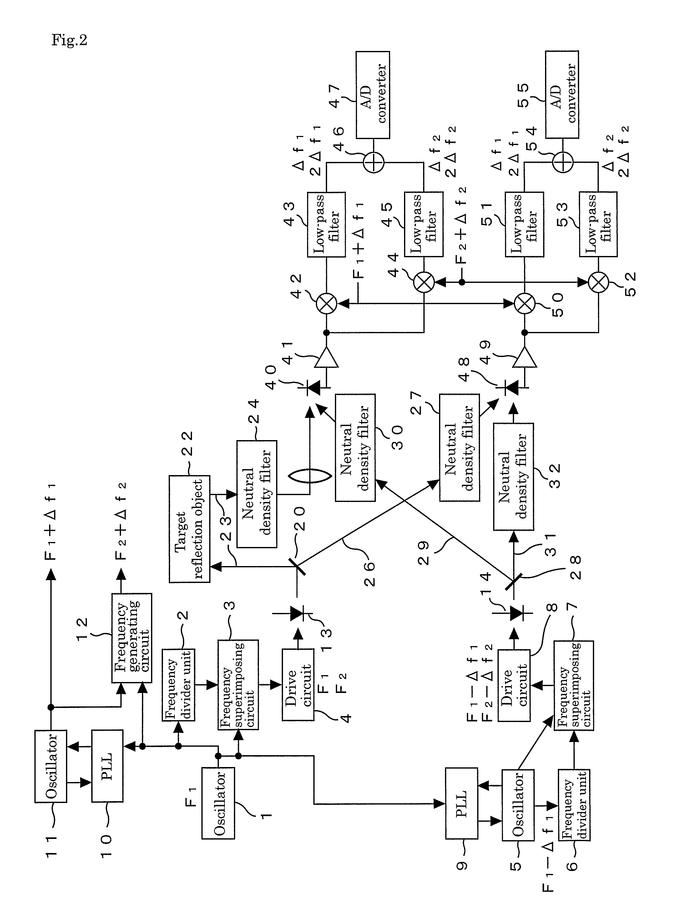
[0027]Hereinafter, an embodiment of an electro-optical distance meter of the present invention will be described in detail based on FIG. 1 to FIG. 3.
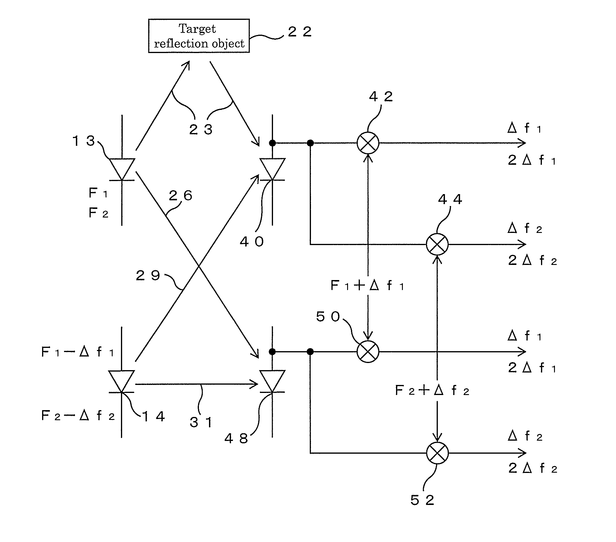
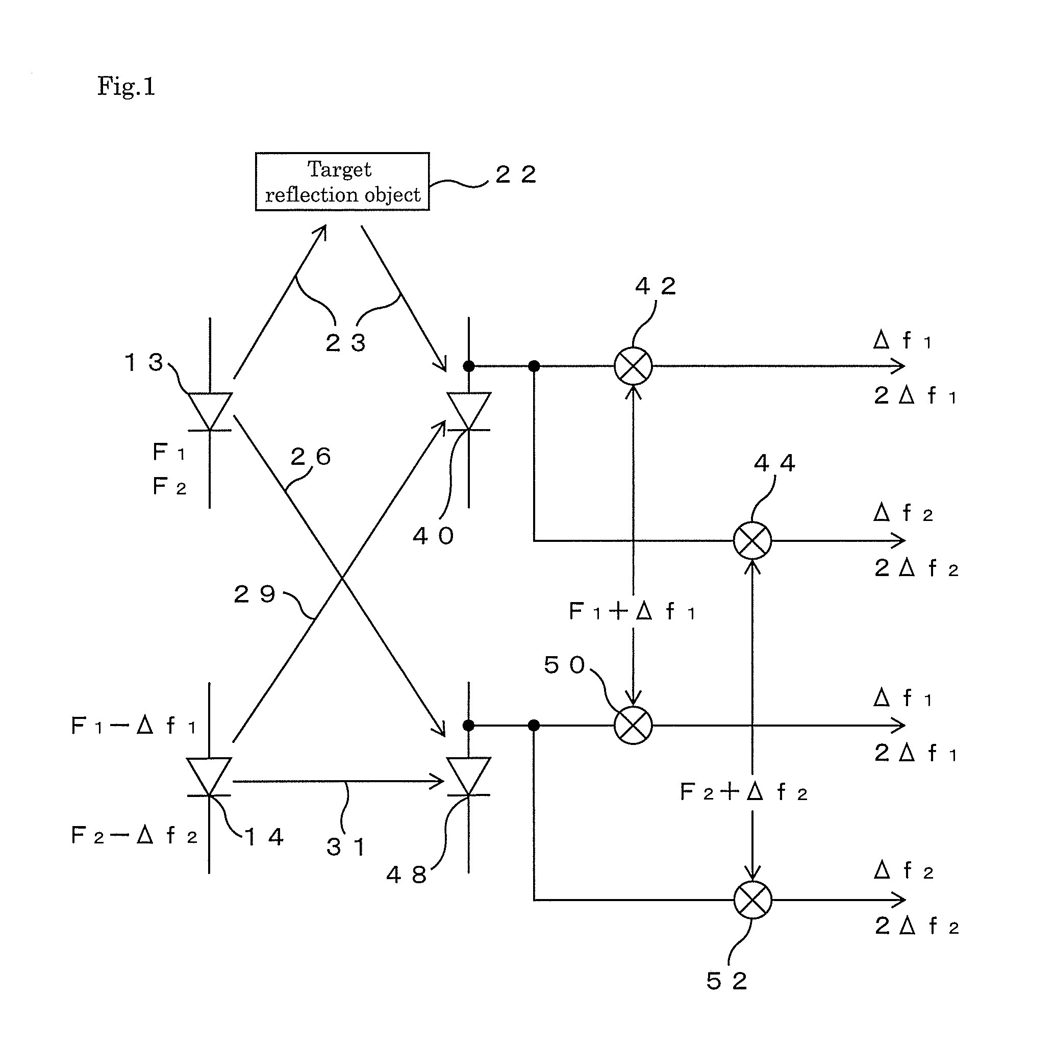
[0028]First, the main part of this electro-optical distance meter will be described based on FIG. 1. This electro-optical distance meter includes two light-emitting elements 13 and 14 such as laser diodes, emits light modulated with frequencies F1 and F2 (hereinafter, referred to as main modulation frequencies) from the first light-emitting element 13, and emits from the second light-emitting element 14 light modulated with frequencies F1−Δf1 and F2−Δf2 (hereinafter, referred to as adjacent modulation frequencies) close to the main modulation frequencies F1 and F2, respectively. The light emitted from the first light-emitting element 13 is split into two parts, one of these is as a distance measuring light made incident onto a first light receiving element 40 through a distance measuring optical path 23 for traveling to and from a targe...
PUM
 Abstract
Description
Claims
Application Information
 - R&D
- Intellectual Property
- Life Sciences
- Materials
- Tech Scout
- Unparalleled Data Quality
- Higher Quality Content
- 60% Fewer Hallucinations
Browse by: Latest US Patents, China's latest patents, Technical Efficacy Thesaurus, Application Domain, Technology Topic, Popular Technical Reports.
© 2025 PatSnap. All rights reserved.Legal|Privacy policy|Modern Slavery Act Transparency Statement|Sitemap|About US| Contact US: help@patsnap.com


