Underlayment with improved drainage

a technology of underlayment and drainage, which is applied in the field of underlayment boards or panels, can solve the problems of further water penetrating the siding and driving water around the joints, and achieve the effects of reducing water penetration to the interior, reducing mold under the exterior finish material, and reducing the rate of drainag

Active Publication Date: 2013-11-05
KINGSPAN INSULATION LLC
View PDF66 Cites 16 Cited by
  • Summary
  • Abstract
  • Description
  • Claims
  • Application Information

AI Technical Summary

Benefits of technology

[0022]Thus, in accordance with the present invention, an underlayment is provided with an increased rate of drainage. The improvements are achieved while maintaining an R value, as desired, as good as underlayments which do not include drainage channels. Such increased drainage can reduce water penetration to the interior of the building, as well as minimize or eliminate mold under the exterior finish material by preventing pooling of water and facilitating air circulation.

Problems solved by technology

The nail or screw holes that result may allow wind blown rain to penetrate the siding.
Vinyl siding may be interlocked together, but heavy rain may drive water around the joints.
Additionally, other avenues of water penetration include seams or cracks along windows, doors, electrical fixtures, water faucets, weep holes and other penetrations in the sidings.
Furthermore, power washing of siding or drainage systems can lead to further water penetrating the siding.

Method used


Image

  • Underlayment with improved drainage
  • Underlayment with improved drainage
  • Underlayment with improved drainage

Examples


Embodiment Construction

[0034]While the present invention will be described with reference to a few specific embodiments, the description is illustrative of the invention and is not to be construed as limiting the invention. Various modifications to the present invention can be made to the preferred embodiments by those skilled in the art without departing from the true spirit and scope of the invention as defined by the appended claims. It will be noted that like components are designated by like reference numerals throughout the various figures.

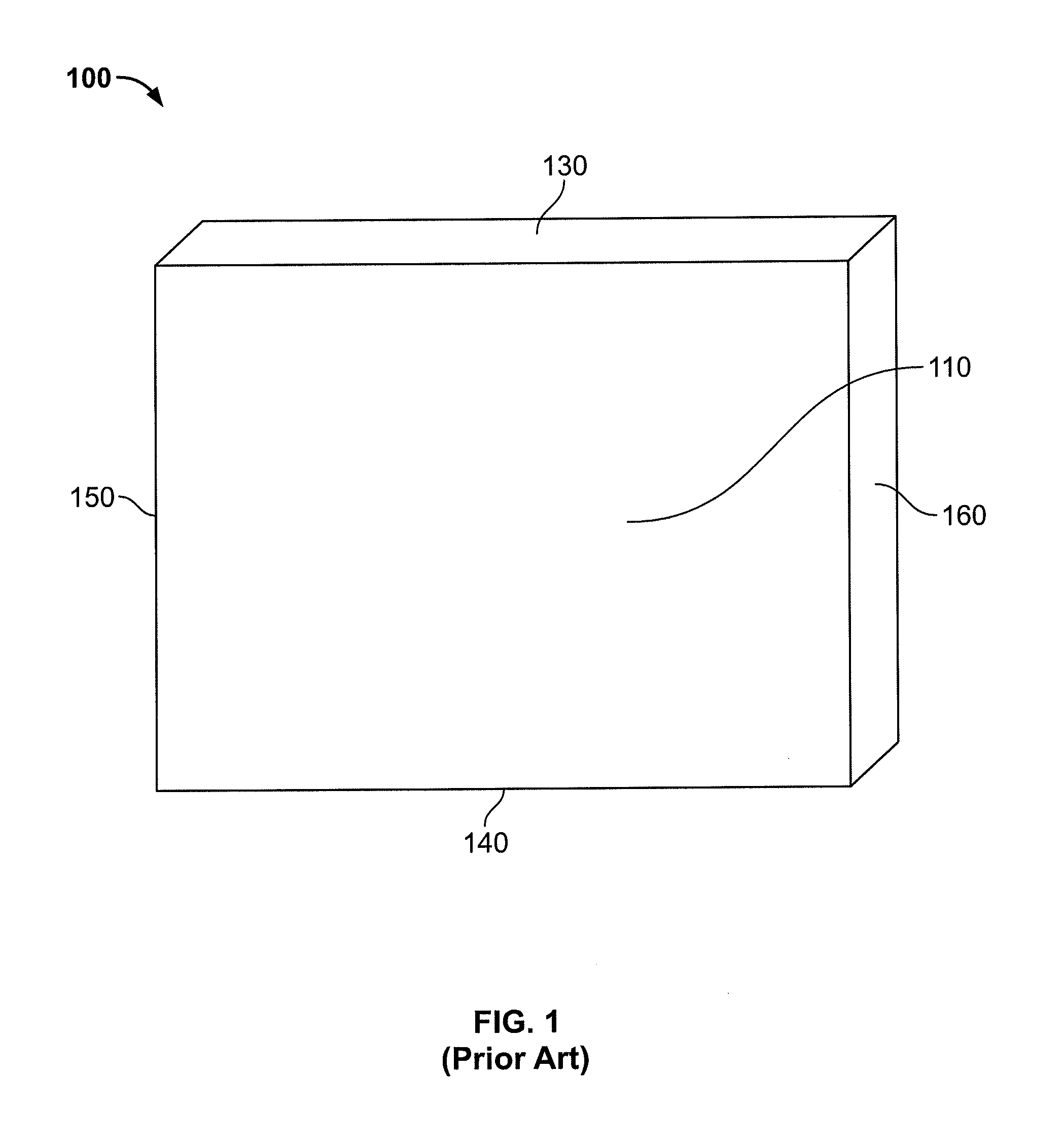
[0035]Referring now to FIG. 1, an underlayment 100 of the prior art is depicted. The underlayment is a rectangular board or panel which includes a first surface 110, a second surface 120 (not shown), a top edge, a bottom edge, and opposing side edges labeled 130, 140, 150, and 160, respectively. Generally, the first and second surfaces are substantially smooth. The board can be made of any known and suitable material.

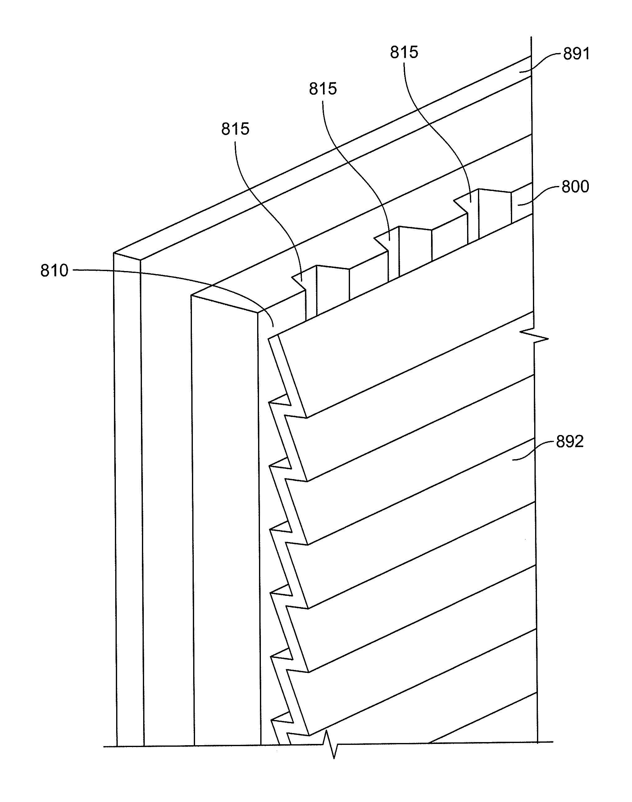
[0036]In accordance with the invention, an unde...


PUM


Abstract

An underlayment with improved drainage is disclosed. Particularly, the invention relates to an underlayment board having a first surface and a second surface, wherein the board further includes a top edge and a bottom edge and includes at least one channel defined in the first surface with each of the at least one channel extending from the top edge to the bottom edge to form a drainage path therebetween. More particularly, the underlayment board can include at least one funnel defined proximate at least the top edge or the bottom edge, wherein the at least one funnel is in fluid communication with a corresponding one of the at least one channel. A method of finishing an exterior of a structural substrate and a building assembly are also disclosed.

Description

CROSS REFERENCE TO RELATED APPLICATIONS[0001]This application claims the benefit of U.S. provisional patent application No. 60 / 837,106 filed on Aug. 11, 2006, the contents of which are expressly incorporated herein by reference thereto.FIELD OF THE INVENTION[0002]The present invention relates generally to underlayments with improved drainage. Particularly, the invention relates to an underlayment board or panel having a first surface and a second surface, wherein the board further includes a top edge, a bottom edge, and at least one channel defined in the first surface. Each of the at least one channel extends from the top edge to the bottom edge to form a drainage path therebetween. More particularly, the underlayment board can include at least one funnel defined proximate the top edge, wherein the at least one funnel is in fluid communication with a corresponding one of the at least one channel.BACKGROUND OF THE INVENTION[0003]The present invention relates to underlayments employe...

Claims


Application Information

Patent Timeline
Patent Type & Authority Patents(United States)
IPC IPC(8): E04F17/00
CPCE04B1/70E04F15/185
Inventor GARTZ, MARK R.LUBKER, II, JOHN W.NORDGREN, DOUGLAS S.EVERETT, PETER JAMES
Owner KINGSPAN INSULATION LLC
Why Eureka
Try Eureka