Tap changer with a polarity switch for a variable transformer

a variable transformer and polarity switch technology, applied in the field of changers, can solve the problems of unacceptable discharge phenomena, unfavorable arc formation, undesired capacitive current switching, etc., and achieve the effect of reducing the degree of arc formation

Active Publication Date: 2013-11-05
MASCHFAB REINHAUSEN GEBR SCHEUBECK GMBH & CO KG
View PDF13 Cites 11 Cited by
  • Summary
  • Abstract
  • Description
  • Claims
  • Application Information

AI Technical Summary

Benefits of technology

[0014]The significant advantage of the two forms of embodiment of the invention consists in that the two polarity resistances provided in accordance with the invention form a bypass for the capacitive current; the capacitive current commutates from one side to the other side and in departure from the prior art it does not have to be switched off, i.e. interrupted, by the preselector. As a consequence, a significantly lower degree of arc formation arises.

Problems solved by technology

The thus-arising difference voltages load the switching path of the opening preselector contacts and can have the consequence of, inter alia, unacceptable discharge phenomena at the preselector.
It is disadvantageous with these known solutions that due to this polarity switching by the preselector the undesired capacitive current is switched, i.e. interrupted; arcs are then inevitable.
These arcs cause formation of gas.
This is undesirable for numerous applications, for example in the case of ultra-high-voltage applications.
These undesired gases are increasingly disruptive with increasing system voltage.

Method used


Image

  • Tap changer with a polarity switch for a variable transformer
  • Tap changer with a polarity switch for a variable transformer
  • Tap changer with a polarity switch for a variable transformer

Examples


first embodiment

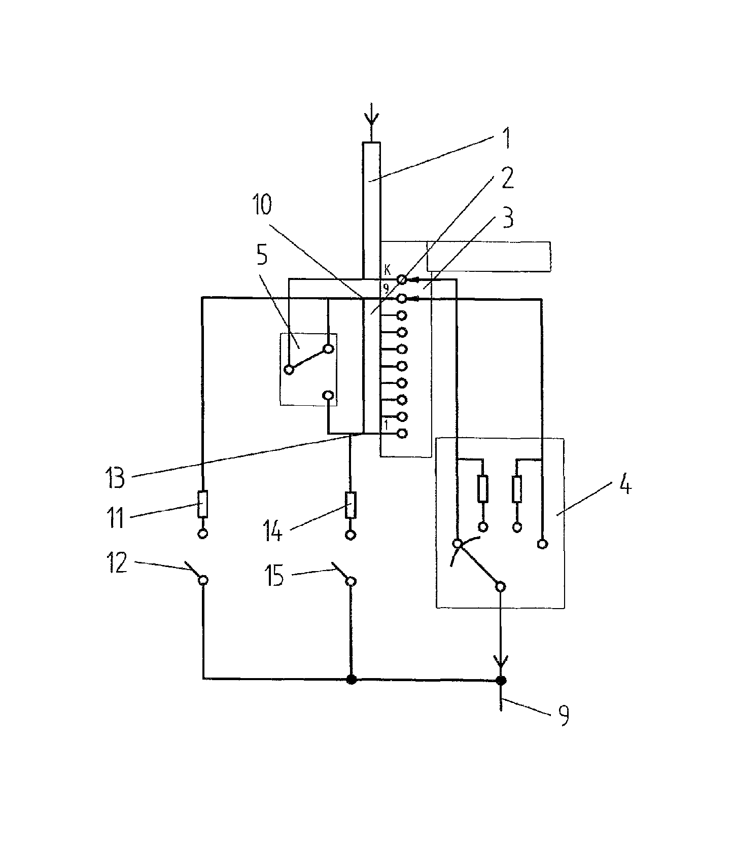
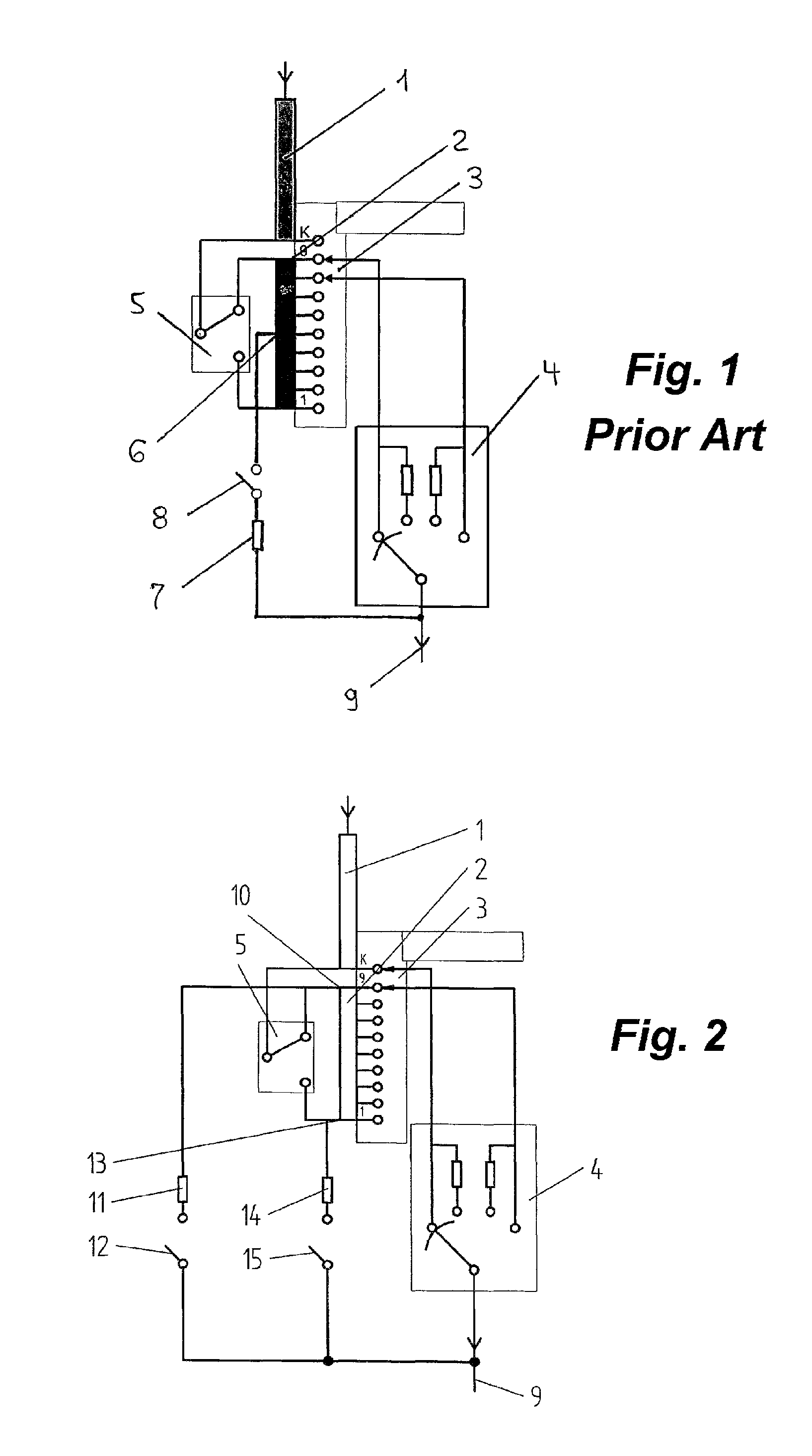
[0021]FIG. 2 shows the invention; the same components are provided with the same reference numerals. In departure from the prior art, according to the invention provided at the start 10 of the tap winding 2 is a first polarity resistance 11 that is connected with the load shunt 9 by a first polarity switch 12. In addition, in accordance with the invention a second polarity resistance 14, which is connected again with the load shunt 9 by a second polarity switch 15, is provided at the end 13 of the tap winding 2. The two polarity switches 12, 15 are switched on only briefly before the start of actuation of the preselector 5, so that the start 10 and end 13 of the tap winding 2 are coupled to a defined potential only temporarily.

second embodiment

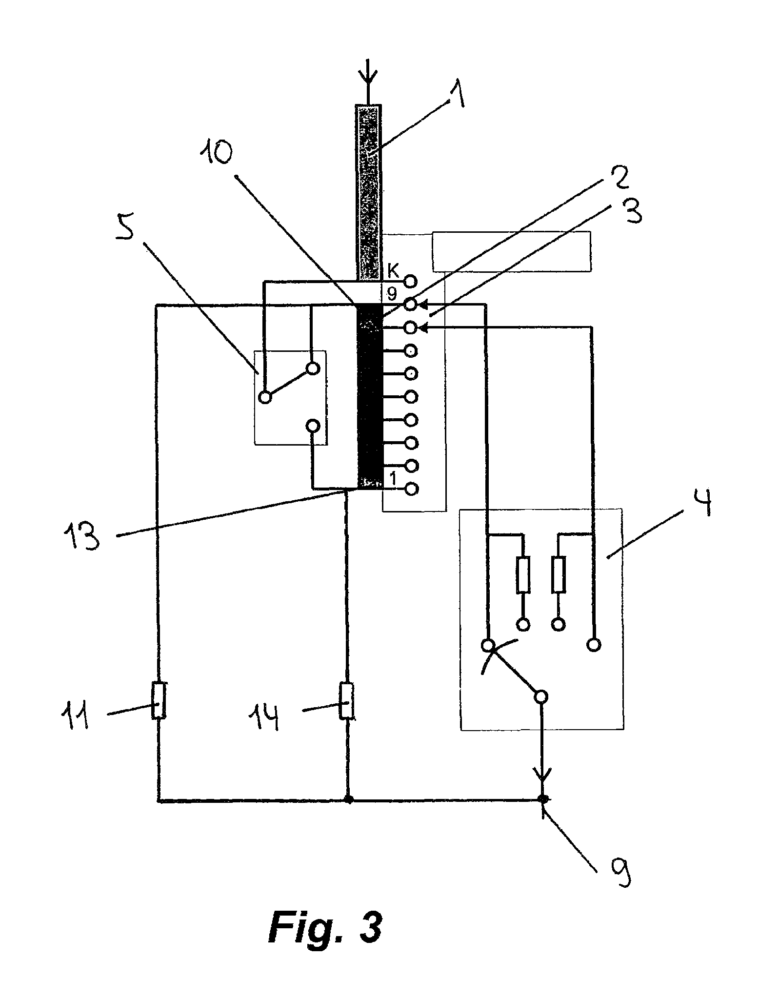
[0022]FIG. 3 shows the invention in which no polarity switches are provided. Rather, here a first polarity resistance 11 is coupled fixedly and permanently to the start of the tap winding 2 and a second polarity switch 14 is coupled fixedly and permanently to the end 13 of the tap winding 2. In this embodiment of the invention the mechanical outlay is less, since, as explained, separate polarity switches are omitted; on the other hand, the disadvantageous higher losses due to permanent connecting-in of the polarity resistances 11, 14 have to be accepted.

[0023]Ultimately, a decision on which of the two variants is a matter of discretion within the scope of the invention. Both forms of embodiments can be realized in single-phase tap changers without substantial effort.

[0024]In particularly advantageous manner, in both forms of embodiment the polarity resistances 11, 14 can be of asymmetrical design so that the specific polarity conditions at respective transformers can be adjusted or ...


PUM

PropertyMeasurementUnit
electrical valuesaaaaaaaaaa
voltagesaaaaaaaaaa
coupling capacitancesaaaaaaaaaa

Abstract

The invention relates to a step switch provided with a preselector and a polarity circuit, a separate polarization resistance being respectively provided at the beginning and the end of the stepped winding. Optionally, the two polarization resistances can be connected continuously or via separate polarity switches.

Description

CROSS REFERENCE TO RELATED APPLICATIONS[0001]This application is the US-national stage of PCT application PCT / EP2010 / 006665 filed 2 Nov. 2010, published 30 Jun. 2011 as 2011 / 076309, and claiming the priority of German patent application 102009060132.5 itself filed 23 Dec. 2009.FIELD OF THE INVENTION[0002]The invention relates to a tap changer provided with a preselector and with a polarity circuit for uninterrupted regulation at a regulating transformer.[0003]DE 19 42 567 [GB 1,267,284] describes a tap changer with a preselector for selectable serial connection of taps of the tap windings with the associated main winding of a tapped transformer, in which the reversing contacts of the tap changer are constructed as changeover contacts.[0004]In such tap changers the tap winding of the corresponding tapped transformer is briefly electrically separated from the main winding during actuation of the preselector. In that case it adopts a potential that results from the voltages of the adja...

Claims


Application Information

Patent Timeline
Patent Type & Authority Patents(United States)
IPC IPC(8): H01F21/12H01F21/02H01F27/28H01F21/08
CPCH01F29/04H01H9/0005H01H33/16
Inventor KRAEMER, AXELSHEN, DAZHONG
Owner MASCHFAB REINHAUSEN GEBR SCHEUBECK GMBH & CO KG
Why Eureka
Try Eureka