Meander antenna device

a portable radio communication and antenna device technology, applied in the direction of collapsable antenna means, resonant antennas, independent non-interacting antenna combinations, etc., can solve the problems of reducing the height of a direction finder antenna, difficult and complicated manufacturing, and less efficient antennas

Inactive Publication Date: 2002-02-26
LAIRD TECH AB (SE)
View PDF15 Cites 61 Cited by
  • Summary
  • Abstract
  • Description
  • Claims
  • Application Information

AI Technical Summary

Benefits of technology

These and other objects are attained by an antenna means in which the first element alternately extends in positive and negative angular directions in relation to the first axis. This radiator geometry has been found to be particularly advantageous with regard to stability, bandwidth and radiating properties. The radiating first element of this antenna means is a meandering conductor which is arched or bent so that it will occupy a space similar to that occupied by a helical radiating element. This configuration enables the antenna means of the invention to be used in most application in radio communication devices, especially for mobile telephones, where helical antennas have been used in the past. In comparison with a helical antenna, the advantages of using the antenna device of the invention are, for example, a greater bandwidth, improved production tolerances leading to less rejections, a lower degree of coupling to any adjacent radiators greatly improving multi-band operability, and a possibility to integrate an impedance matching network on the same carrier with at least partly the same production technique. The radiating element alternately extending in positive and negative angular directions in relation to its central axis, should be understood as including the radiating element describing a meander curve changing circumferential direction at least once in its extension along a longitudinal axis of an imaginary cylindrical shell, preferably having a circular or elliptic base.
When the antenna means includes one or more additional radiating element(s), operability within a wider frequency band or two or more separated frequency bands is achieved. It is possible to produce all radiating elements simultaneously in the same sequence of process steps.
The antenna device preferably includes a dielectric carrier carrying the radiating structure to project it outwards from a chassis of a radio communication device on which the device is to be mounted. This enables an efficient radiation pattern. The carrier is preferably a dielectric flexible film or laminate having the radiating structure applied thereon or therein in the form of a conductive film structure, possibly obtained through an etching process. A printing technique is suitable for manufacturing in large quantities.
It may be advantageous to combine the antenna means according to the invention with an extendable and retractable whip antenna, as will be appreciated from the following description of preferred embodiments. The carrier and conductors of the antenna means will then possibly include one or more switches for connecting or disconnecting different radiating elements in different operating modes.
Especially when the carrier is a flexible film with a printed circuit pattern it is advantageous to integrate on the carrier an impedance matching means for matching impedances of any radiating element on the film or in combination with that structure to circuitry of the radio communication device, usually interfacing at 50 ohms.

Problems solved by technology

That prior art antenna device has the inherent drawbacks of helical antennas, and is difficult and complicated to manufacture because of the need to provide feed-throughs in the substrate or joining conductors at edges.
Although relatively efficient and compact, there is a great variety of prior art antenna devices that involve the above-mentioned problems due to the use of helical radiators.
The problem to be solved thereby is reducing the height of a direction finder antenna, in particular to render it concealable and mobile However, it only discloses a meander antenna which has a flat configuration.
Moreover, the teachings thereof include improving the bandwidth of the antenna by using a conductor having relatively high resistance, leading to a less efficient antenna.
Further, there are no provisions for obtaining a mechanically durable antenna, an antenna suited to fit in a limited volume or an antenna to be combined with other types of antennas.

Method used


Image

  • Meander antenna device
  • Meander antenna device
  • Meander antenna device

Examples


Embodiment Construction

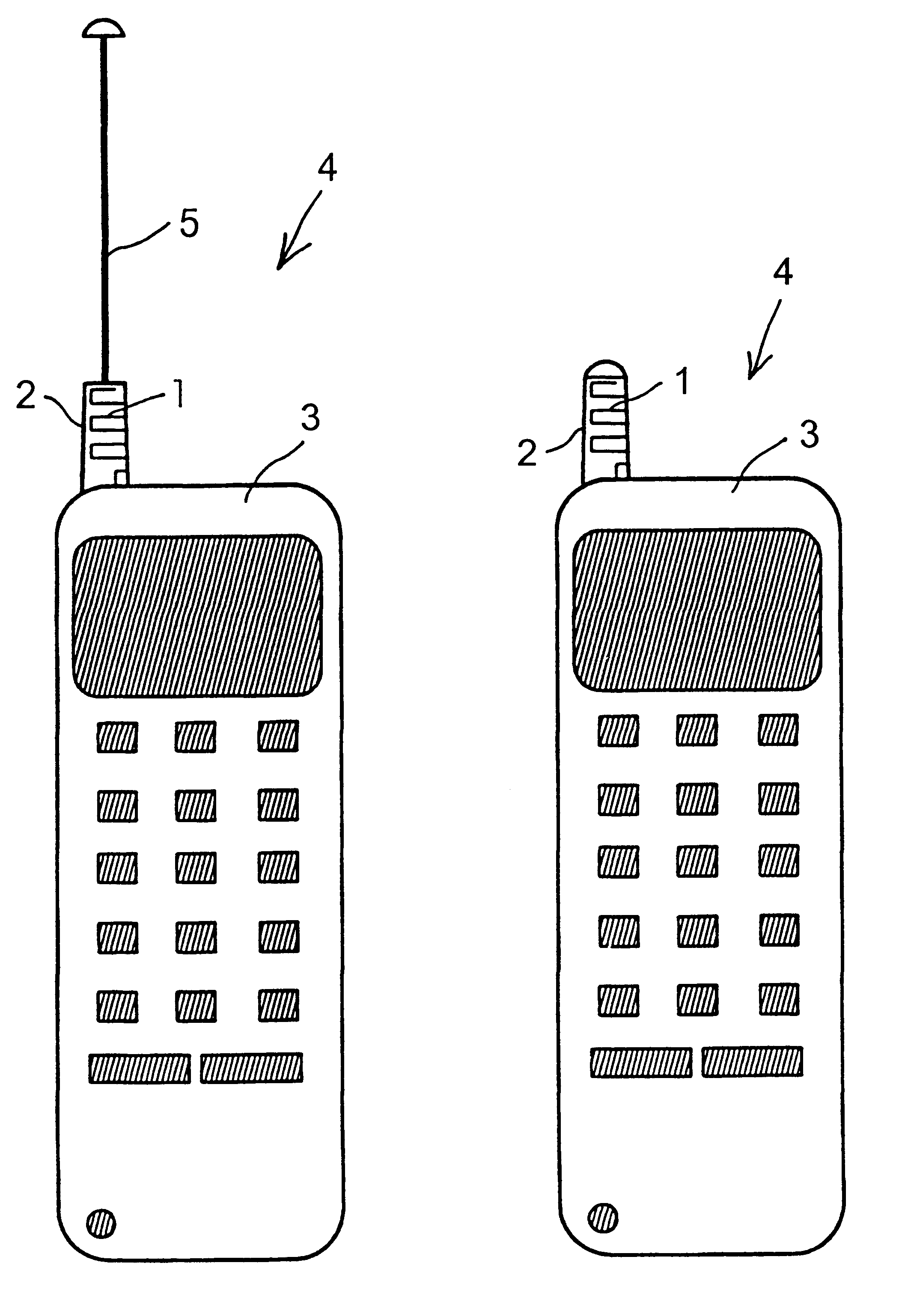
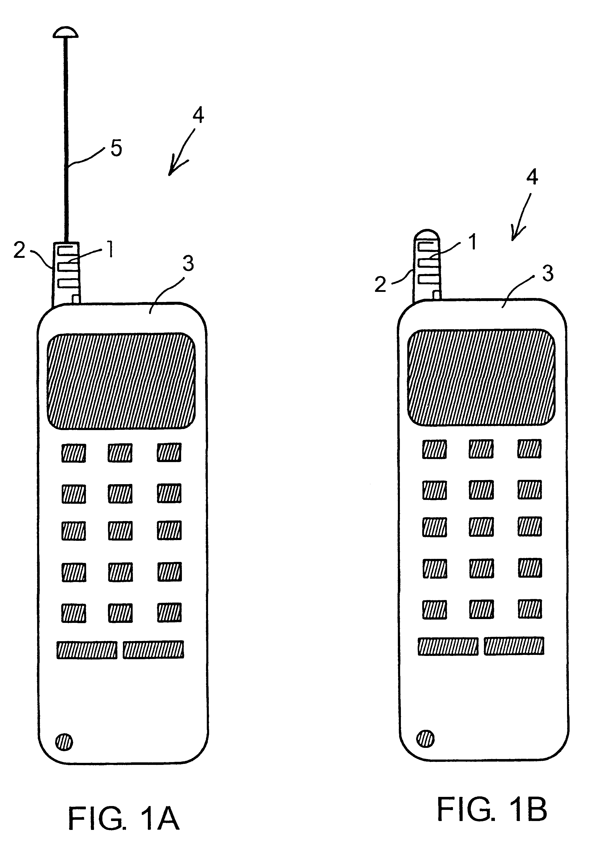
With reference to FIG. 1A, a meander radiating element 1 is carried by a dielectric cylindrical carrier 2 and mounted extending outwards on a chassis 3 of a hand portable mobile telephone 4. The position of the meander element 1 on the chassis 3 is selected such that radiation of the meander conductor 1 is transmitted and received effectively in different positions chosen by an operator during standby or during a telephone call. In FIGS. 1A-B the meander element is located at one side of a top portion of the chassis 3 projecting upwards.

Also shown in FIG. 1A is an extendable and retractable whip antenna 5 shown in its extended position. There may or may not be a whip antenna combined with the meander element, depending on the antenna performance required in a specific case. FIG. 1B shows the arrangement of FIG. 1A having the whip antenna in its retracted position.

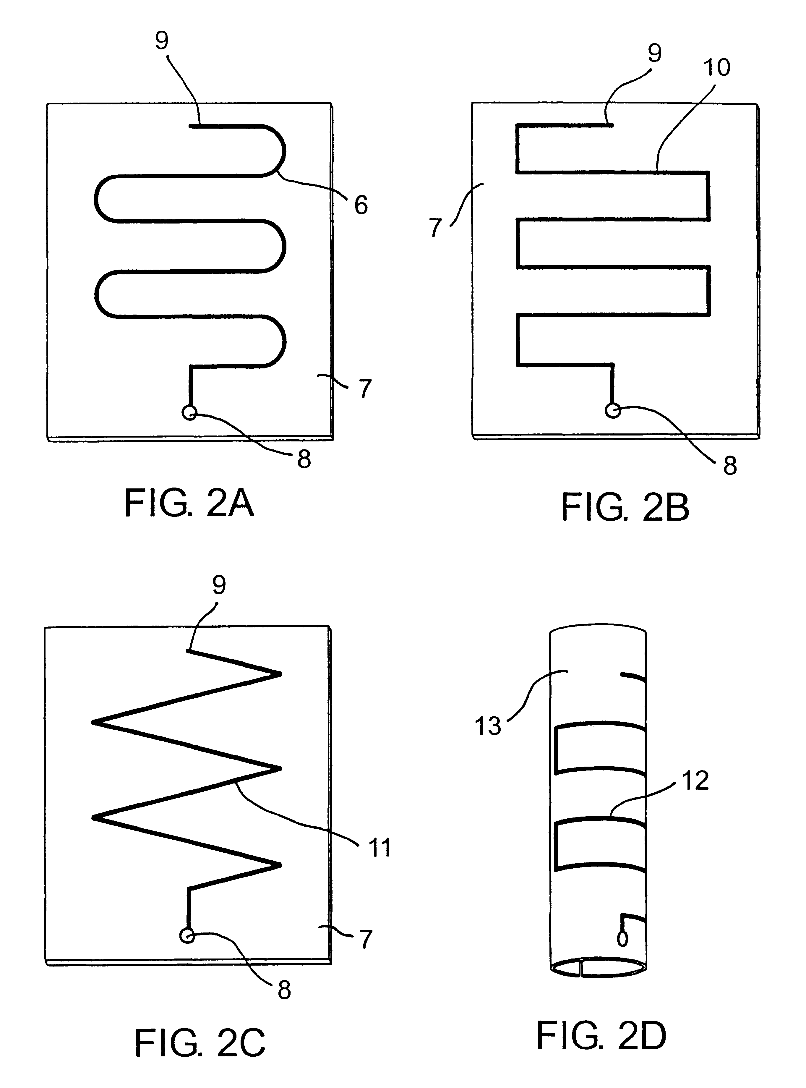
FIG. 2A shows a first possible shape 6 of the meander radiating element being an etched conductor pattern on a dielectric...


PUM


Abstract

An antenna means for a portable radio communication device, in particular a hand-portable mobile telephone, having at least one radiating element that has a meandering and cylindrical configuration. This structure is specifically advantageous in combination with an extendable and retractable whip antenna and, when having two or more meandering radiating elements, in multi-band radiating structures. The antenna device is suitable for manufacturing in large quantities, for example by a flexible printed circuit board technique.

Description

1. Field of the InventionThe present invention relates to an antenna means for a portable radio communication device, comprising a radiating first element tuned to a first frequency, the first element having a central longitudinal first axis, first and second ends being a first feed point and a first open end, respectively, and a meander configuration. Specifically, the invention concerns an antenna means for a hand-portable mobile telephone, which requires a compact and efficient antenna. The inventive antenna means is particularly advantageous when two or more radiating elements are to be combined or when an impedance matching means is required for matching radiating element(s) of the antenna means to transmitter / receiver circuitry of the telephone.A general problem that occurs when the size of an antenna radiator is reduced is a reduction in its relative bandwidth. Helically configured radiators are commonly used when antennas are required to fit in confined volumes with limited ...

Claims


Application Information

Patent Timeline
Patent Type & Authority Patents(United States)
IPC IPC(8): H01Q1/24H01Q1/36H01Q1/10H01Q21/28H01Q1/27H01Q5/10H01Q9/42
CPCH01Q1/36H01Q1/244
Inventor WASS, BO
Owner LAIRD TECH AB (SE)
Why Eureka
Try Eureka