Posting server, content transmission system, and posting server control method

a content transmission system and server technology, applied in the direction of digital output to print units, electrical apparatus, pictoral communication, etc., can solve the problems of facsimile delivery system, unsatisfactory cost increase, and long delivery time, and achieve the effect of high quality

Active Publication Date: 2013-11-05
SEIKO EPSON CORP
View PDF65 Cites 4 Cited by
  • Summary
  • Abstract
  • Description
  • Claims
  • Application Information

AI Technical Summary

Benefits of technology

[0010]There would thus be a demand for low-cost and high-quality delivery of print contents.
[0013]The printing terminal creates the delivery result information regarding the delivered content data and transmits the created delivery result information to the posting server. The posting server according to one aspect of the invention receives the transmitted delivery result information, adds the received delivery result information to the delivery record information stored in the storage unit, and notifies the sending terminal of at least part of the delivery record information. This arrangement enables the sending terminal to refer to the notified information and check whether the delivered print content is actually printed, thus enhancing the reliability of delivery of the content data.
[0023]In the content transmission system according to this aspect of the invention, the printing terminal creates the delivery result information regarding the delivered content data and transmits the created delivery result information to the posting server. The posting server receives the transmitted delivery result information, adds the received delivery result information to the delivery record information stored in the storage unit, and notifies the sending terminal of at least part of the delivery record information. This arrangement enables the sending terminal to refer to the notified information and check whether the delivered print content is actually printed, thus enhancing the reliability of delivery of the content data.

Problems solved by technology

The mail delivery system, however, requires the large manpower for the mail delivery, thus undesirably increasing the cost and taking rather long time for the delivery.
The facsimile delivery system, however, still needs the communication cost and does not provide the customers or students with the high-quality print contents.

Method used


Image

  • Posting server, content transmission system, and posting server control method
  • Posting server, content transmission system, and posting server control method
  • Posting server, content transmission system, and posting server control method

Examples


first embodiment

A. First Embodiment

A-1. System Configuration

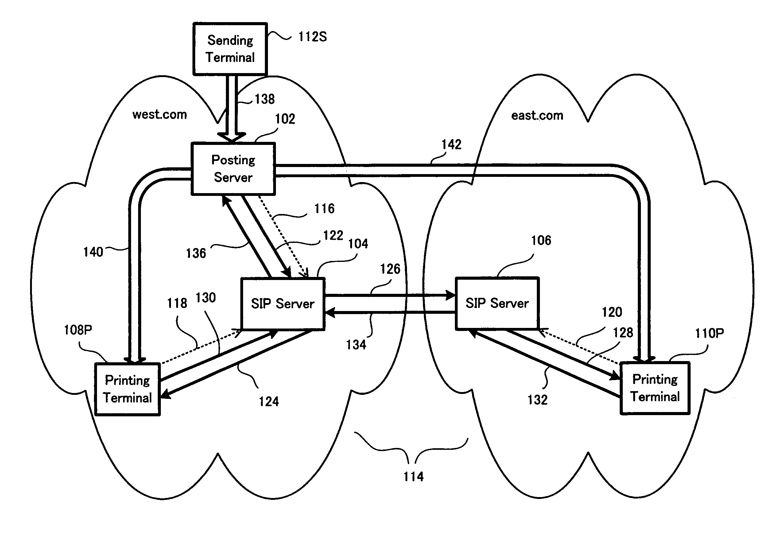
[0072]FIG. 1 is a block diagram schematically illustrating the configuration of a content transmission system in a first embodiment of the invention.

[0073]As shown in FIG. 1, the content transmission system of the first embodiment includes a sending terminal 112S managed by a company desiring delivery of print contents (for example, advertisements or materials for distance learning), a posting server 102 and SIP (Session Initiation Protocol) servers 104 and 106 managed by at least one network service provider, and printing terminals 108P and 110P managed by individual customers. The posing server 102 and the SIP servers 104 and 106 may be managed by different network service providers or may be managed by one identical network service provider. The posting server 102, the SIP servers 104 and 106, and the printing terminals 108P and 110P are interconnected via a broadband network 114, such as the Internet. The sending terminal 112S may be c...

second embodiment

B. Second Embodiment

B-1. System Configuration

[0111]FIG. 7 is a block diagram schematically illustrating the configuration of a content transmission system in a second embodiment of the invention.

[0112]As shown in FIG. 7, the difference of the content transmission system of the second embodiment from the content transmission system of the first embodiment is that a sending terminal 144S managed by the company desiring delivery of print contents directly delivers content data to the printing terminals 108P and 110P managed by the individual customers without using a posting server. Namely the sending terminal 144S managed by the company has the functions of the posting server. The posting server 102 included in the content transmission system of FIG. 1 is thus omitted from the content transmission system of FIG. 7. Otherwise the content transmission system of the second embodiment has the similar configuration to that of the content transmission system of the first embodiment. The sam...

third embodiment

C. Third Embodiment

C-1. System Configuration

[0119]FIG. 8 is a block diagram schematically illustrating the configuration of a content transmission system in a third embodiment of the invention.

[0120]As shown in FIG. 8, the difference of the content transmission system of the third embodiment from the content transmission system of the first embodiment is to enable transmission of print contents between customers. In the content transmission system of the third embodiment, a sending terminal 108S managed by one customer is arranged to enable direct transmission of content data to a printing terminal 110P managed by another customer. The sending terminal 108S may be identical with the printing terminal 108P or may be different from the printing terminal 108P. In the former case, for example, a complex machine may be used as both the sending terminal and the printing terminal. In another example of the former case, both a scanner and a printer are connected ton one personal computer. T...


PUM


Abstract

A printing terminal 208P creates delivery result information regarding delivered content data and transmits the created delivery result information to a posting server 202. The posting server 202 receives the transmitted delivery result information, adds the received delivery result information to delivery record information stored in a memory, and notifies a sending terminal of at least part of the delivery record information. This arrangement enables low-cost and high-quality delivery of print contents.

Description

BACKGROUND OF THE INVENTION[0001]1. Field of the Invention[0002]The present invention relates to a technique of transmitting content data for printing a content via a network. In the specification hereof, the terminology of ‘print content’ or ‘content’ means any of various pieces of information including documents, images, and their combinations and especially refers to printable information. The ‘content data’ means data representing such a content.[0003]2. Description of the Related Art[0004]A company generally delivers advertisements to its customers by mail or by facsimile. The mail and the facsimile are also used for delivery of materials for distance learning from a correspondence organization to its students.[0005]The mail delivery system provides the respective customers or students with high-quality prints of advertisements or materials as print contents. The mail delivery system, however, requires the large manpower for the mail delivery, thus undesirably increasing the co...

Claims


Application Information

Patent Timeline
Patent Type & Authority Patents(United States)
IPC IPC(8): G06F15/16
CPCH04N1/00214H04N1/00217H04N1/00244H04N1/32122H04N2201/0082H04N2201/3218H04N2201/3274H04N2201/3278G06F3/12G06F15/16
Inventor YODA, KIYOSHINAGAO, KATSUNORINISHITANI, MASANOBUKUBOTA, EIJIOZAWA, TAKAO
Owner SEIKO EPSON CORP
Why Eureka
Try Eureka