Method for the flying changing of working rolls in continuous casting and rolling installations and hot strip rolling mills using a hold-down roller

a technology of continuous casting and rolling, which is applied in the direction of rolling mill control devices, tension/compression control devices, manufacturing tools, etc., can solve the problems of loss of production, loss of quality of the surface of rolled strips, and inability to prevent loss of production,

Active Publication Date: 2013-11-12
SMS DEMAG AG
View PDF17 Cites 1 Cited by
  • Summary
  • Abstract
  • Description
  • Claims
  • Application Information

AI Technical Summary

Benefits of technology

[0019]It makes sense to carry out strip monitoring during rolling. This serves for identifying a strip region which would be rolled during the roll exchange. This information is necessary when during the roll exchange, e.g., the temperature or the thickness regulation cannot be adequately maintained for process-technical reason

Problems solved by technology

Working rolls of a rolling stand are naturally subjected to wear which can lead to quality loss of the surface of a rolled strip.
Therefore, the loss of production is not prevented.
A continuous casting and rolling operation with long casting runs is not possible without loss of quality of the strip surface.
In CSP continuous operation, this is not possible

Method used


Image

  • Method for the flying changing of working rolls in continuous casting and rolling installations and hot strip rolling mills using a hold-down roller
  • Method for the flying changing of working rolls in continuous casting and rolling installations and hot strip rolling mills using a hold-down roller

Examples


Embodiment Construction

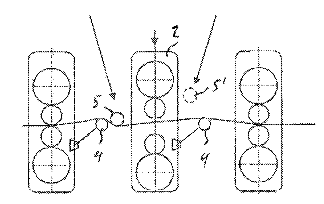
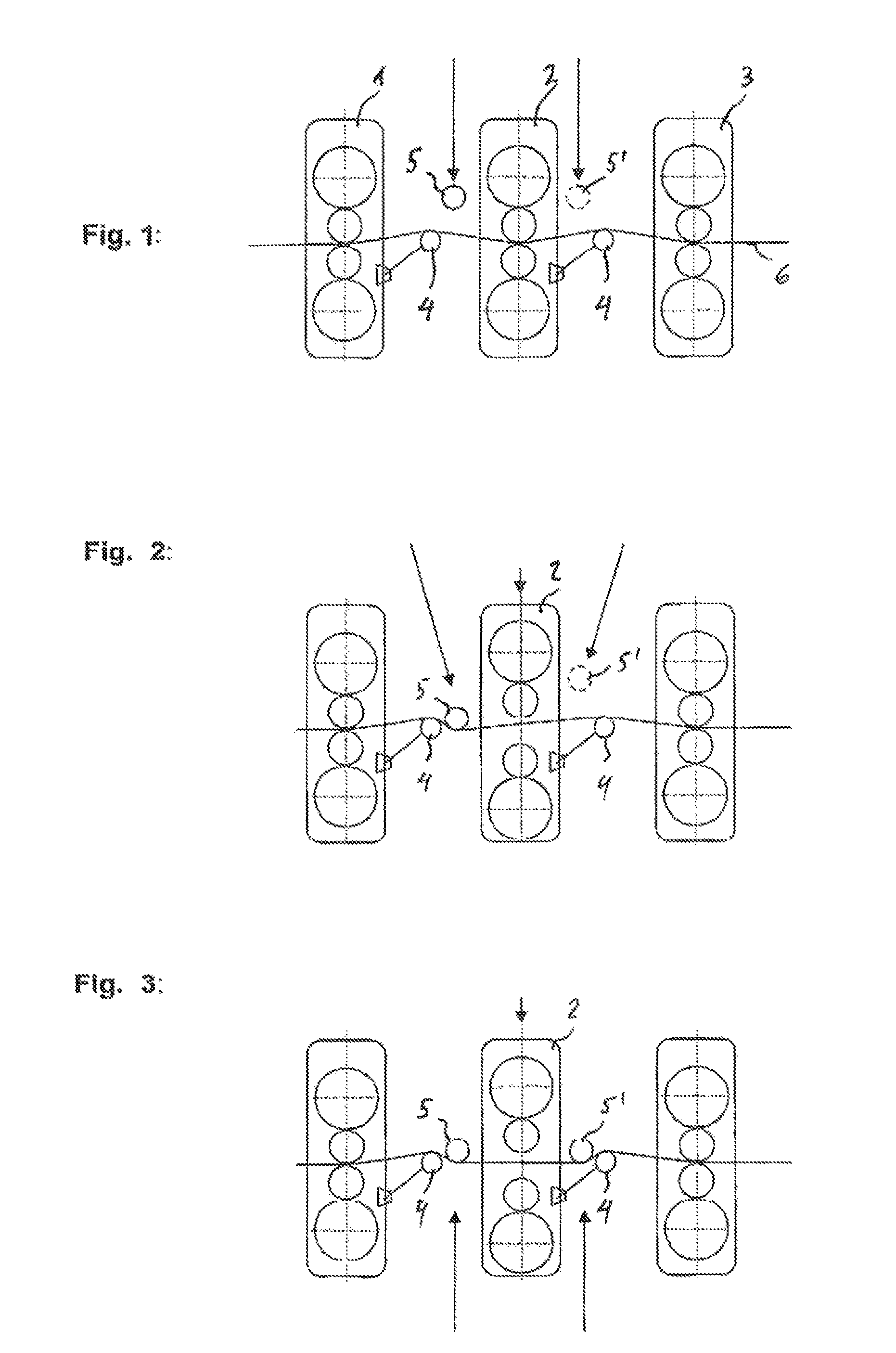
[0026]Between rolling stands 1, 2 and 3, a conventional loop lifter 4 with which the strip tension is adjusted, is located. During a normal rolling process, as shown in FIG. 1, neither a hold-down roller 5 located in front of the rolling stand 2, nor a hold-down roller 5′ located behind the rolling stand, when available, engage the hot strip 6.

[0027]In order, e.g., to change the working rolls in the middle rolling stand 2, the rolls should be lifted, as shown in FIG. 2.

[0028]Because the hot strip does not have any contact with working rolls, at least the hold-down roller 5 which is located in front of the rolling stand 2 becomes active, together with the loop lifter 4 associated with this hold-down roller, so that the hot strip can be displaced, without contacting the working rolls, through the open rolling stand with the corresponding strip tension.

[0029]The flying changing of the working rolls itself can be effected with conventional devices.

[0030]Thus, e.g., the working roll pair...


PUM

PropertyMeasurementUnit
Temperatureaaaaaaaaaa
Tensionaaaaaaaaaa

Abstract

The invention relates to a method of flying changing of working rolls in continuous casting and rolling installations and hot strip rolling mills, in particular in continuous hot strip rolling mills, wherein for exchange of working rolls by opening a rolling stand, those are disengaged from a to be rolled hot strip. According to the invention a regulated strip tension that can substitute the tension of the open rolling stand, is applied to the to-be-rolled hot strip with at least one hold-down roller that is introduced in a rolling line.

Description

RELATED APPLICATIONS[0001]This application is a National Stage application of PCT application PCT / EP2011 / 055307 filed on Apr. 6, 2011 and based on German Priority application DE 10 2010 014346 filed Apr. 9, 2010, both applications being incorporated herein by reference thereto.BACKGROUND OF THE INVENTION[0002]1. Field of the Invention[0003]The invention relates to a method of flying changing of working rolls in continuous casting and rolling installations and hot strip rolling mills, in particular in continuous hot strip rolling trains.[0004]2. Description of the Prior Art[0005]Working rolls of a rolling stand are naturally subjected to wear which can lead to quality loss of the surface of a rolled strip.[0006]To prevent this, an exchange of rolls is needed from time to time.[0007]For hot rolling, to-be-rolled strip should be heated to a necessary temperature, this being the case even when it is rolled immediately after casting. When a short furnace is used without a buffer or the f...

Claims


Application Information

Patent Timeline
IPC IPC(8): B21B37/48B21B31/08
CPCB21B31/08B21B31/12B21B39/08
Inventor KLEIN, CHRISTOPHBENFER, FRANKWINDHAUS, ERNST
Owner SMS DEMAG AG
Why Eureka
Try Eureka