Physical quantity sensor including bonding wire with vibration isolation performance characteristics

a technology of vibration isolation and physical quantity, applied in the direction of acceleration measurement using interia force, turn-sensitive devices, instruments, etc., can solve the problems of increasing the noise contained in the output of the sensing portion, difficult to ensure sufficient structural strength of the resin spring, and difficult to achieve desirable vibration isolation performance, etc., to achieve sufficient vibration isolation performance and improve structural strength and durability

Active Publication Date: 2013-11-12
DENSO CORP
View PDF41 Cites 3 Cited by
  • Summary
  • Abstract
  • Description
  • Claims
  • Application Information

AI Technical Summary

Benefits of technology

[0008]The present invention is made in view of the aforementioned drawbacks, and it is an object of the present invention to provide a physical quantity sensor having a bonding wire with improved structural strength and durability while ensuring sufficient vibration isolation performance.
[0009]According to an aspect of the present invention, a physical quantity sensor includes a sensing portion having an end wall, a casing, a vibration isolating member, an electrically conductive portion, a pad, and a bonding wire. The casing has a support portion for supporting the sensing portion. The support portion has a support surface opposed to the end wall of the sensing portion. The vibration isolating member is disposed between the end wall of the sensing portion and the support surface of the support portion to join the sensing portion to the casing. The vibration insulating member is configured to reduce a relative vibration between the sensing portion and the casing. The electrically conductive portion is provided on the casing. The pad is provided on the sensing portion. The bonding wire electrically connects the electrically conductive portion and the pad. The bonding wire extends from the pad to the electrically conductive portion while bending opposite to the support surface. The bonding wire is configured to satisfy a relation of 20×d≦h, in which d is an outer diameter of the bonding wire and h is a height of the bonding wire from the pad to a furthest point of the bend from the pad with respect to a direction perpendicular to the support surface. In the structure, the vibration isolating member is disposed between the support portion and the end wall of the sensing portion. The relative vibration between the casing and the sensing portion is reduced by the vibration isolating member. Further, the bonding wire is configured so that deformation of the bonding wire is reduced even if a relative displacement between the sensing portion and the casing occurs. Accordingly, structural strength and durability of the bonding wire improve, and vibration isolation performance is ensured.
[0010]According to a second aspect of the present invention, a physical quantity sensor includes a sensing portion, a casing, a vibration isolating member, an electrically conductive portion, a pad, and a bonding wire. The casing encases the sensing portion therein. The casing provides a clearance between an inner surface thereof and an outer wall of the sensing portion. The vibration isolating member is disposed in at least a portion of the clearance to join the sensing portion to the casing. The vibration isolating member is configured to reduce a relative vibration between the sensing portion and the casing. The electrically conductive portion is provided on the casing. The pad is provided on a surface of the sensing portion. The bonding wire electrically connects the electrically conductive portion and the pad. The bonding wire extends from the pad to the electrically conductive portion and includes a bend. The bonding wire is configured to satisfy a relation of 20×d≦h, in which d is an outer diameter of the bonding wire, and h is a height of the bonding wire from the pad to a furthest point of the bend from the pad with respect to a direction perpendicular to the surface of the sensing portion.
[0011]In the structure, the vibration isolating member is disposed between the sensing portion and the casing to join the sensing portion to the casing. The relative vibration between the casing and the sensing portion is reduced by the vibration isolating member. Further, the bonding wire is configured so that deformation of the bonding wire is reduced even if a relative displacement between the sensing portion and the casing occurs. Accordingly, structural strength and durability of the bonding wire improve, and vibration isolation performance is ensured.
[0012]According to a third aspect of the present invention, a physical quantity sensor includes a sensing portion, a casing, a vibration isolating member, an electrically conductive portion, a pad and a bonding wire. The casing encases the sensing portion therein. The vibration isolating member is disposed between the sensing portion and the casing to hold the sensing portion within the casing and to reduce a relative vibration between the sensing portion and the casing. The electrically conductive portion is provided on the casing. The pad is provided on a surface of the sensing portion. The bonding wire electrically connects the electrically conductive portion and the pad. The bonding wire extends from the pad substantially perpendicular to the surface of the sensing portion, bends to extend substantially parallel to the surface of the sensing portion, and connects to the electrically conductive portion. The bonding wire is configured to satisfy a relation of 20×d≦h, in which d is an outer diameter of the bonding wire, and h is a dimension of the bonding wire from the pad to a furthest point of a bend with respect to a direction perpendicular to the surface of the sensing portion.
[0013]In the structure, the vibration isolating member is disposed between the sensing portion and the casing to join the sensing portion to the casing. The relative vibration between the casing and the sensing portion is reduced by the vibration isolating member. Further, the bonding wire is configured so that deformation of the bonding wire is reduced even if a relative displacement between the sensing portion and the casing occurs. Accordingly, structural strength and durability of the bonding wire improve, and vibration isolation performance is ensured.

Problems solved by technology

In such a physical quantity sensor, if a vibration of the casing is transmitted to the sensing portion, a noise contained in an output of the sensing portion increases.
Further, it is difficult to ensure sufficient structural strength of the resin spring.
Such a measurement, however, will affect the vibration isolation performance, and thus it may be difficult to achieve desirable vibration isolation performance.

Method used


Image

  • Physical quantity sensor including bonding wire with vibration isolation performance characteristics
  • Physical quantity sensor including bonding wire with vibration isolation performance characteristics
  • Physical quantity sensor including bonding wire with vibration isolation performance characteristics

Examples


first embodiment

[0039](First Embodiment)

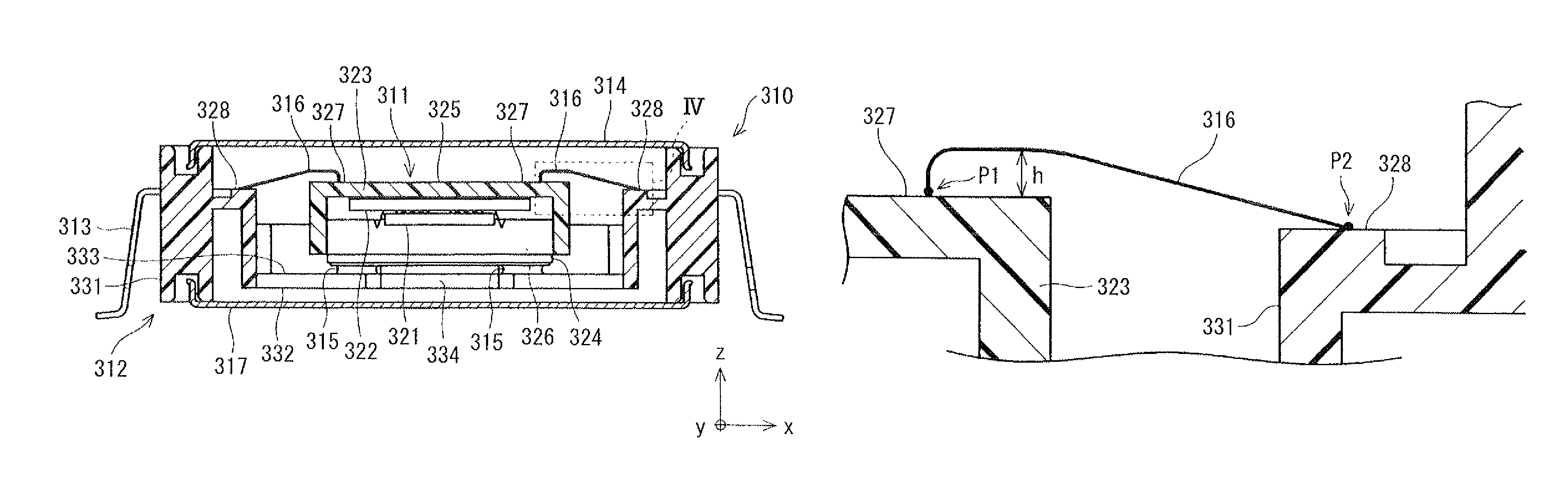
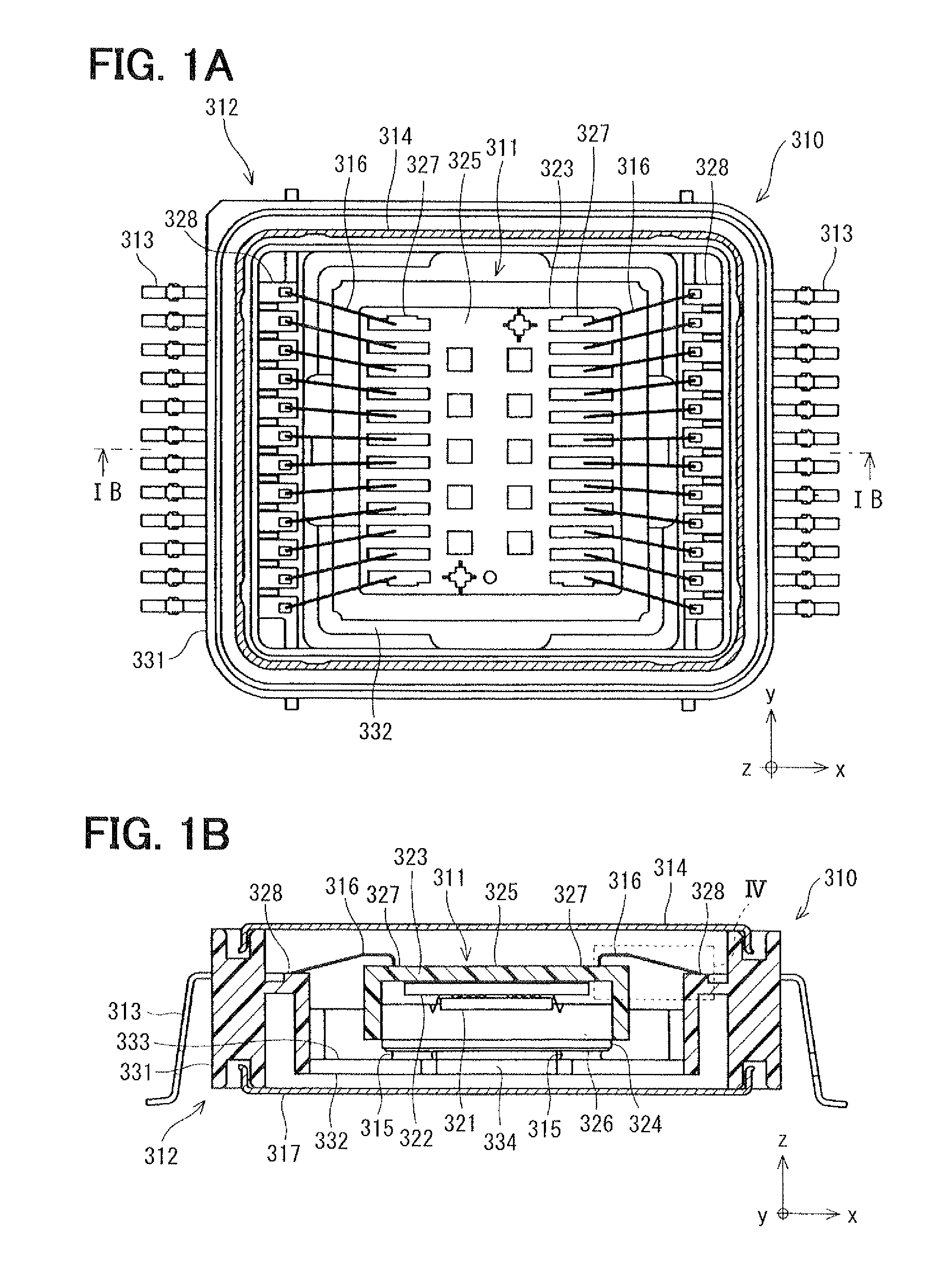
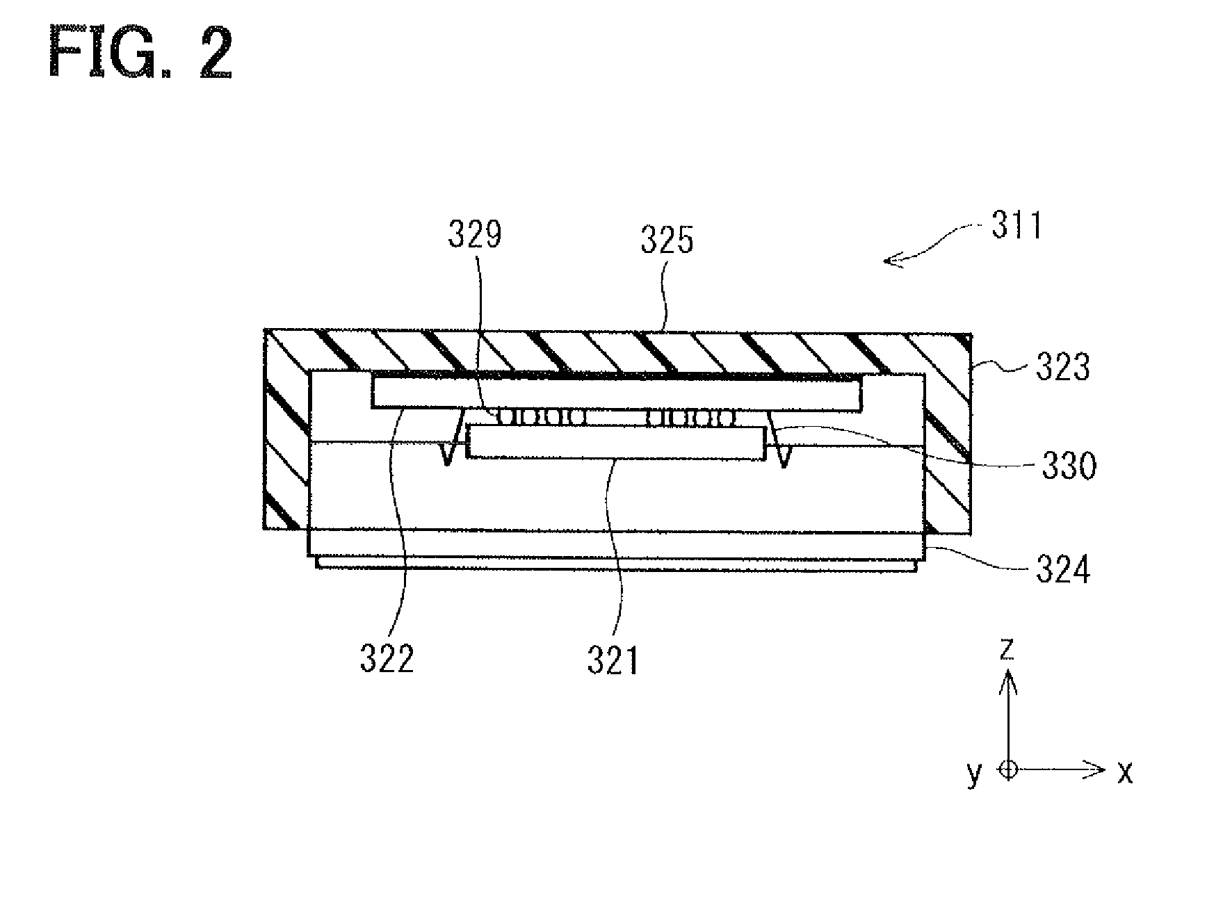
[0040]FIGS. 1A and 1B show a physical quantity sensor 310 according to a first embodiment of the present invention. The physical quantity sensor 310 includes an inner unit 311 as a sensing portion, a casing 312, lead frames 313, a cover 314, a vibration isolating member 315, bonding wires 316, and a cover 317. As shown in FIG. 2, the inner unit 311 includes a sensor chip 321, a signal processing chip 322, a housing body 323 and a lid 324.

[0041]The physical quantity sensor 310 is applicable to any one of an angular velocity sensor, an acceleration sensor and an inertia force sensor. That is, the physical quantity sensor 310 can be configured to be any one of the angular velocity sensor, the acceleration sensor and the inertia force sensor. The angular velocity sensor detects an angular velocity in a direction of rotation centering an axis of the sensing portion. The acceleration sensor detects an acceleration applied to the sensing portion. The inertia force s...

second embodiment

[0112](Second Embodiment)

[0113]FIGS. 17A and 17B shows a physical quantity sensor 410 according to a second embodiment. As shown in FIG. 17A, the physical quantity sensor 410 includes an inner unit 411 as a sensing portion, a casing 412, lead frames 413, a cover 414, a vibration isolating member 415, bonding wires 416 and a cover 417.

[0114]As shown in FIG. 18, the inner unit 411 has a sensor chip 421, a signal processing chip 422, a package 423 and a lid 424. The sensor chip 421 has a substantially same structure as the sensor chip 321 shown in FIG. 3.

[0115]The signal processing chip 422 performs signal processing on a capacitance or voltage change detected by the sensor chip 421, and adjusts a voltage applied to the sensor chip 421. The sensor chip 421 and the signal processing chip 422 are, for example, formed on silicon or ceramic substrates. As an detection object, for example, the sensor chip 421 detects an angular velocity or acceleration in directions along the X axis and / or ...


PUM


Abstract

A physical quantity sensor includes a sensing portion, a casing, a vibration isolating member, an electrically conductive portion, a pad and a bonding wire. The casing encases the sensing portion therein. The vibration isolating member is disposed between the sensing portion and the casing to reduce a relative vibration between the sensing portion and the casing. The bonding wire electrically connects the electrically conductive portion provided on the casing and the pad provided on a surface of the sensing portion. The bonding wire extends from the pad to the electrically conductive portion and includes a bend. The bonding wire is configured to satisfy a relation of 20×d≦h, in which d is an outer diameter of the bonding wire, and h is a dimension of the bonding wire with respect to a direction perpendicular to the surface of the sensing portion.

Description

CROSS REFERENCE TO RELATED APPLICATION[0001]This application is based on Japanese Patent Application No. 2010-4871 filed on Jan. 13, 2010, the disclosure of which is incorporated herein by reference.FIELD OF THE INVENTION[0002]The present invention relates to a physical quantity sensor. More particularly, the present invention relates to a physical quantity sensor having a sensing portion held in a casing.BACKGROUND OF THE INVENTION[0003]A physical quantity sensor has a sensing portion formed with a substrate such as a semiconductor substrate or a ceramic substrate. The sensing portion is held in a casing made of a resin, for example. The sensing portion detects a physical quantity, such as angular velocity, acceleration, and turning power, based on a change in an electrical capacitance, a voltage, or the like.[0004]In such a physical quantity sensor, if a vibration of the casing is transmitted to the sensing portion, a noise contained in an output of the sensing portion increases. ...

Claims


Application Information

Patent Timeline
Patent Type & Authority Patents(United States)
IPC IPC(8): G01P1/02G01P15/125G01C19/56G01C19/5747G01C19/5769G01C19/5783G01P15/08H01L29/84
CPCB81B7/0058G01C19/5769G01P1/023G01P15/125B81B2201/0242H01L2224/48465
Inventor OHTA, TAMEHARUSHINODA, TAKESHIISHII, ITARUNAKANO, KEISUKE
Owner DENSO CORP
Why Eureka
Try Eureka