Sliding bearing for internal combustion engine

a technology for sliding bearings and internal combustion engines, which is applied to sliding contact bearings, mechanical equipment, rotary machine parts, etc., can solve the problems of increasing the possibility of sliding surface damage and increasing the possibility, so as to reduce the conformability of bearings, reduce the amount of lubricant oil leakage, and reduce the effect of load capacity

Active Publication Date: 2013-11-12
DAIDO METAL CO LTD
View PDF9 Cites 2 Cited by
  • Summary
  • Abstract
  • Description
  • Claims
  • Application Information

AI Technical Summary

Benefits of technology

[0009]At the time of the initial operation of an internal combustion engine, foreign matters remaining in the lubricant oil path tend to enter the lubricant oil which is supplied to the circumferential oil groove of the sliding bearing for the crankshaft. The foreign matters mean metalwork chippings produced during the cutting work of the oil path, molding sand used in casting process, and the like. Foreign matters accompany the flow of the lubricant oil due to the rotation of the crankshaft. In the conventional sliding bearing for an internal combustion engine, foreign matters are discharged to the outside of the bearing together with the lubricant oil through clearance portions in a crush relief, a chamfer, and the like which are formed at the circumferential end portion of the bearing. However, since the rotational speed of the crankshaft in the internal combustion engines has been increased recently, the inertia force becomes large which acts on the foreign matters having specific gravities larger than that of the lubricant oil (foreign matters move forward along the circumferential direction by the inertia force). Therefore, the foreign matters are not discharged from the clearance portion in the combined end surfaces of the sliding bearing (combined end surfaces of a pair of semi-cylindrical bearings), and enter the sliding surface of the sliding bearing (the other semi-cylindrical bearing) which does not have an oil groove. This increases the possibility of damage of the bearing sliding surface due to the foreign matters.
[0010]Meanwhile, sliding bearings are proposed in which a narrowed portion is formed in the oil groove in the circumferential end portion of a semi-cylindrical bearing, in order to decrease the leakage amount of the lubricant oil from the circumferential end portion of the bearing (see JP-A-2005-69283). Studying these sliding bearings from the viewpoint of the aforementioned foreign matters, there is the problem that the flow velocity of the lubricant oil increases at the downstream of the narrowed portion with respect to the flowing direction of the lubricant oil, and then the aforementioned inertia force which acts on the foreign matters accompanying the lubricant oil becomes larger correspondingly, and this further increases the possibility of the entry of the foreign matters to the bearing sliding portion of the other semi-cylindrical bearing in which the oil groove is not formed.
[0011]Thus, an object of the present invention is to provide a sliding bearing for an internal combustion engine, which is excellent in capability of discharging foreign matters.
[0020]In order to enhance the load capacity by facilitating oil film formation for the first curved surface which receives a large load by the operation of the internal combustion engine, the depths of the circumferential grooves of the first curved surface are preferably made smaller than the depths of the circumferential grooves of the second curved surface.
[0025]In order to guide the lubricant oil and foreign matters, which are dispersed into the gap portion made by the second curved surface and the crankshaft, to the axial groove for the lubricant oil, the circumferential grooves may be formed to have the groove depths of between 4 μm and 15 μm with pitches of between 0.1 mm and 0.8 mm. If the depths of the circumferential grooves are less than 4 μm and the pitches of the circumferential grooves (circumferential groove widths) are less than 0.1 mm, the lubricant oil and the foreign matters easily go out from the inside of the circumferential grooves. If the circumferential groove depths exceed 15 μm, and the pitches (circumferential groove widths) of the circumferential grooves exceed 0.8 mm, the cross-sectional area per one ridge in the vicinity of the apex of the crest portion of each of the circumferential grooves becomes too large, and when contact with the crankshaft occurs, the apex of the crest portion hardly wears to reduce conformability of the bearing.
[0026]The circumferential grooves of the first curved surface are made to have groove depths of 3 μm or less with pitches of between 0.1 mm and 0.8 mm. By the configuration, an oil film is easily formed on the first curved surface, and load capacity can be enhanced.

Problems solved by technology

This increases the possibility of damage of the bearing sliding surface due to the foreign matters.
Studying these sliding bearings from the viewpoint of the aforementioned foreign matters, there is the problem that the flow velocity of the lubricant oil increases at the downstream of the narrowed portion with respect to the flowing direction of the lubricant oil, and then the aforementioned inertia force which acts on the foreign matters accompanying the lubricant oil becomes larger correspondingly, and this further increases the possibility of the entry of the foreign matters to the bearing sliding portion of the other semi-cylindrical bearing in which the oil groove is not formed.

Method used


Image

  • Sliding bearing for internal combustion engine
  • Sliding bearing for internal combustion engine
  • Sliding bearing for internal combustion engine

Examples


example

[0034]Hereinafter, an embodiment of the present invention will be described with reference to the attached drawings.

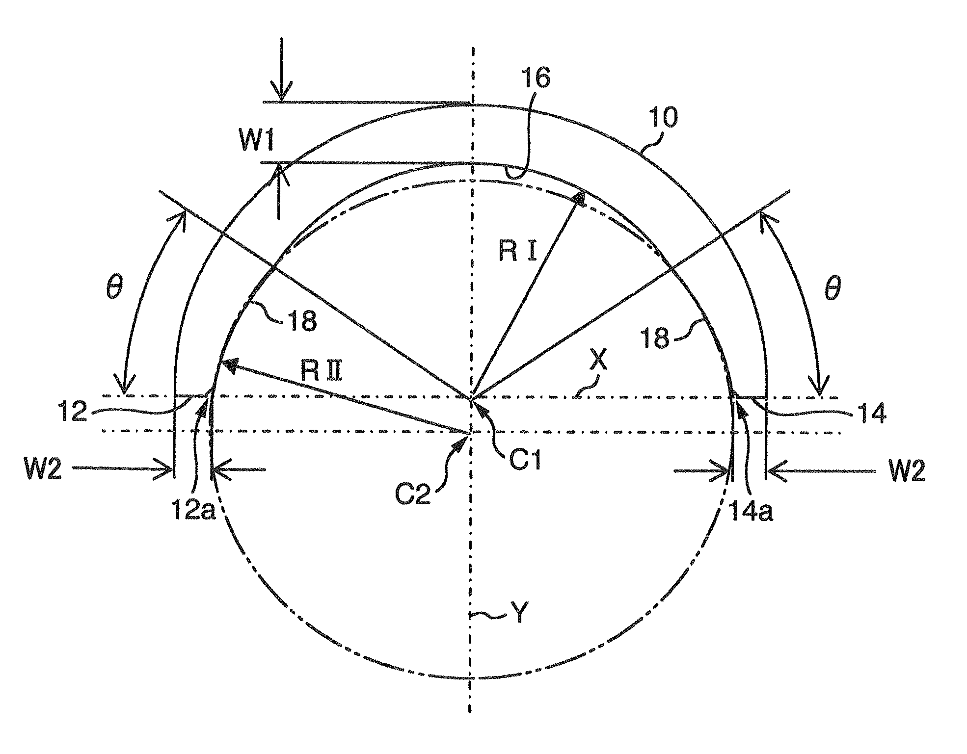
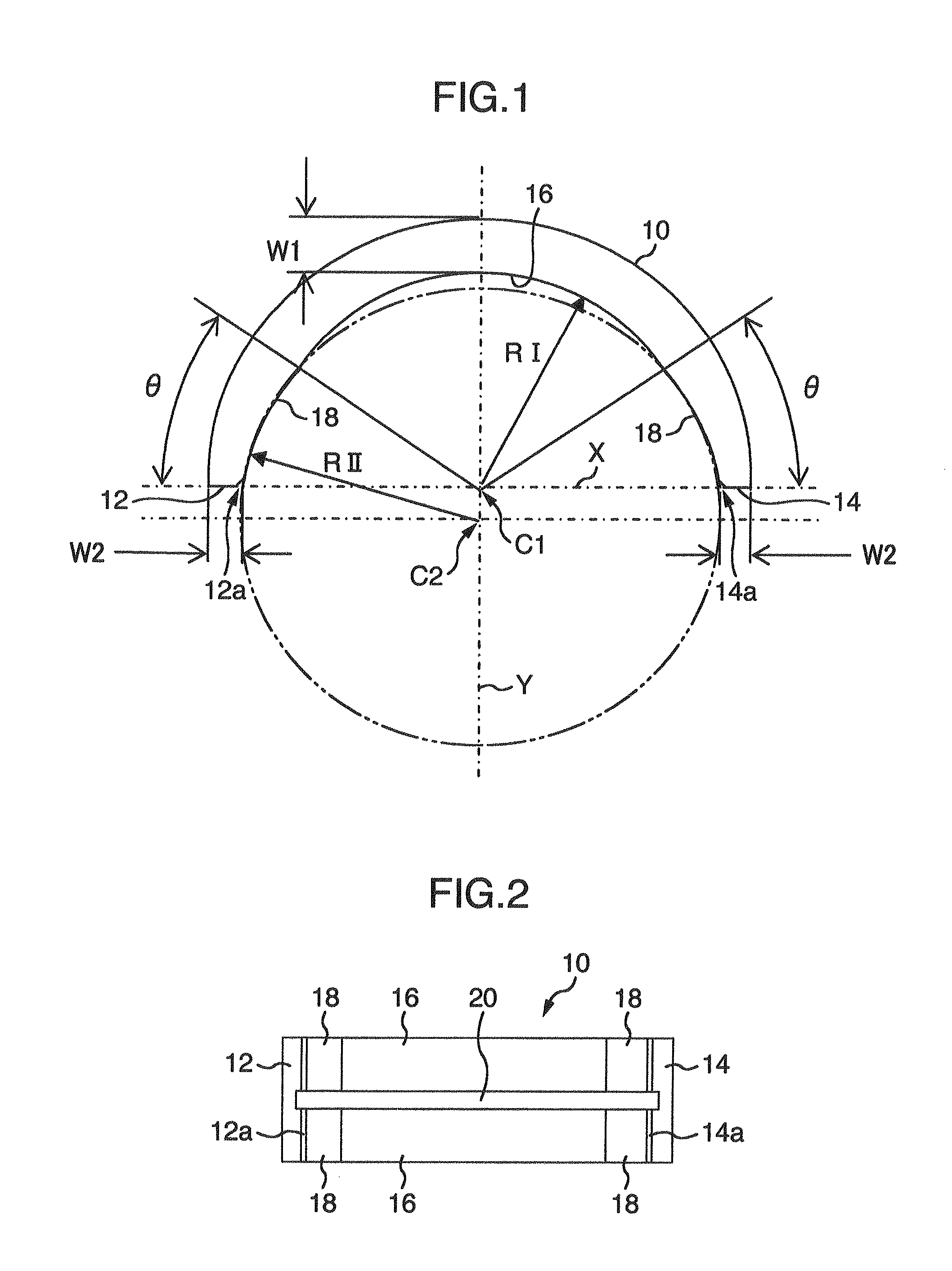
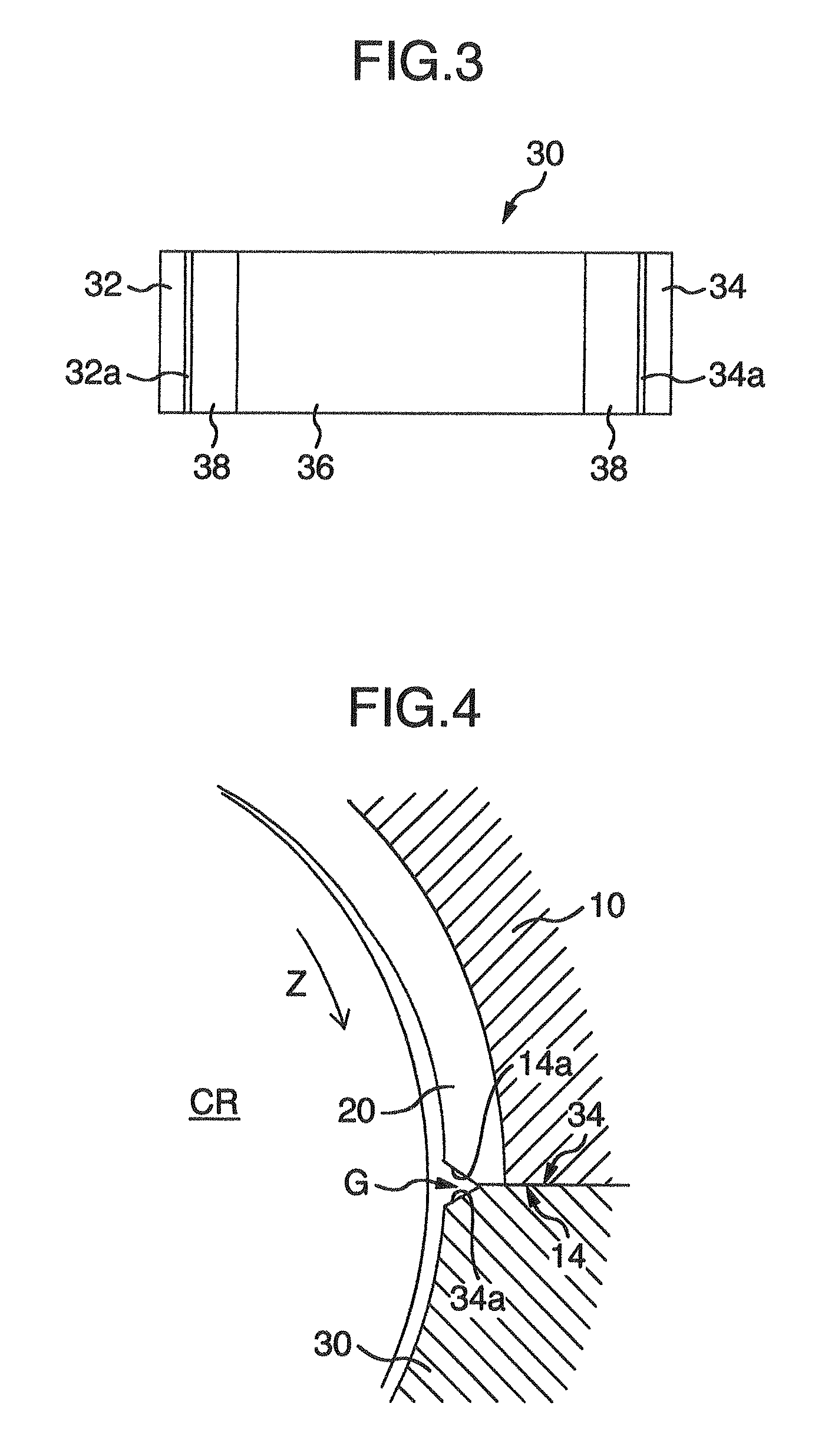
[0035]FIG. 1 is a view showing a semi-cylindrical bearing 10 for supporting a crankshaft of an internal combustion engine according to one embodiment of the present invention, which is shown from its axial direction. FIG. 2 is a view showing a bearing inner circumferential surface of the semi-cylindrical bearing 10. The semi-cylindrical bearing 10 is combined with the other semi-cylindrical bearing 30 (FIG. 3) in a substantially the same shape into a cylindrical shape to be a sliding bearing for a crankshaft. The difference between the both semi-cylindrical bearings 10 and 30 is that a circumferential oil groove 20 is formed in the central portion of the bearing width of the inner circumferential surface of the semi-cylindrical bearing 10 all over the entire length in the circumferential direction. The other structures of the both semi-cylindrical bearings 10 and 30 ar...


PUM


Abstract

Disclosed is a sliding bearing for an internal combustion engine for supporting a crankshaft including a pair of semi-cylindrical bearings combined with each other into a cylindrical body. Each of inner circumferential surfaces of the respective semi-cylindrical bearings includes first and second curved surfaces following two kinds of arcs with different curvatures. The first curved surface is in a region including a circumferential central portion of the inner circumferential surface. The second curved surfaces are in remaining two regions of the inner circumferential surface. The circumferential oil groove and the axial groove communicate with each other. The circumferential grooves of the second curved surfaces and the axial groove communicate with each other. The groove bottoms of the circumferential grooves of the second curved surfaces are displaced to a side of the bearing inner circumferential surface from a groove bottom of the axial groove.

Description

INCORPORATION BY REFERENCE[0001]The present application claims priority from JP Patent Application Ser. No. 2009-209173 filed on Sep. 10, 2009, the content of which is hereby incorporated by reference into this application.BACKGROUND OF THE INVENTION[0002](1) Field of the Invention[0003]The present invention relates to a sliding bearing for an internal combustion engine in which a pair of semi-cylindrical bearings is combined with each other into a cylindrical shape to support a crankshaft.[0004](2) Description of the Related Art[0005]Conventionally, a sliding bearing formed into a cylindrical shape by combining two semi-cylindrical bearings is used for a crankshaft. A circumferential oil groove is formed on a bearing inner surface of at least one of a pair of semi-cylindrical bearings, and oil is supplied to an outer circumferential surface of a crankpin via the circumferential oil groove (see JP-A-8-277831).[0006]Meanwhile, in recent years, in order to decrease the leakage amount ...

Claims


Application Information

Patent Timeline
Patent Type & Authority Patents(United States)
IPC IPC(8): F16C9/02
CPCF16C9/02F16C17/246F16C33/1065F16C33/046F16C17/022F16C2240/40F16C2240/42F16C2240/54F16C2360/22F16C2240/30F16C2240/60F16C2240/70
Inventor ISHIGO, OSAMUOKADO, ATSUSHI
Owner DAIDO METAL CO LTD
Why Eureka
Try Eureka