Bone reduction and plate clamp assembly

a technology of plate clamping and bone reduction, which is applied in the field of bone reduction and plate clamping assembly, can solve the problems of not revealing the same or similar elements, nor presenting the material components in a manner

Inactive Publication Date: 2013-11-12
JORDAN CHRISTOPHER
View PDF16 Cites 16 Cited by
  • Summary
  • Abstract
  • Description
  • Claims
  • Application Information

AI Technical Summary

Benefits of technology

[0012]The disclosed bone clamps and accessory assembly provide for a pair of clamps to be used to align and secure a broken bone for reduction and hold the broken bone in proper alignment and further provide for the secure placement of one or more bone plates across the fracture site being repaired. The clamps are provided with two clamp sections, each section defining a clamping end, and handle end and a central connection section where the two clamp sections are attached together in a pivotal scissor configuration with the clamping ends directed towards each other forming

Problems solved by technology

However, the prior art inventions do not disclose the same or similar elements as the present bone and plate clamp assembly, nor do they present the material components in a manner contemplated or anticipated in the prior art.
None of the above disclosed sone clamps or alignment devices provide a means to secure two bone segments using a scissored clamping force with a locking means to retain the clamp into its clamped position, provide a secondary clamping means to secure each bone clamp to a common alignment bar which may be independently attached to each clamp prior to or subsequent to the clamps being secured to respective bone sections for subsequent linear a

Method used


Image

  • Bone reduction and plate clamp assembly
  • Bone reduction and plate clamp assembly
  • Bone reduction and plate clamp assembly

Examples


Embodiment Construction

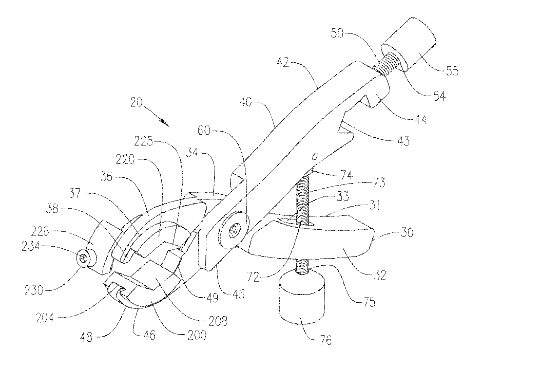
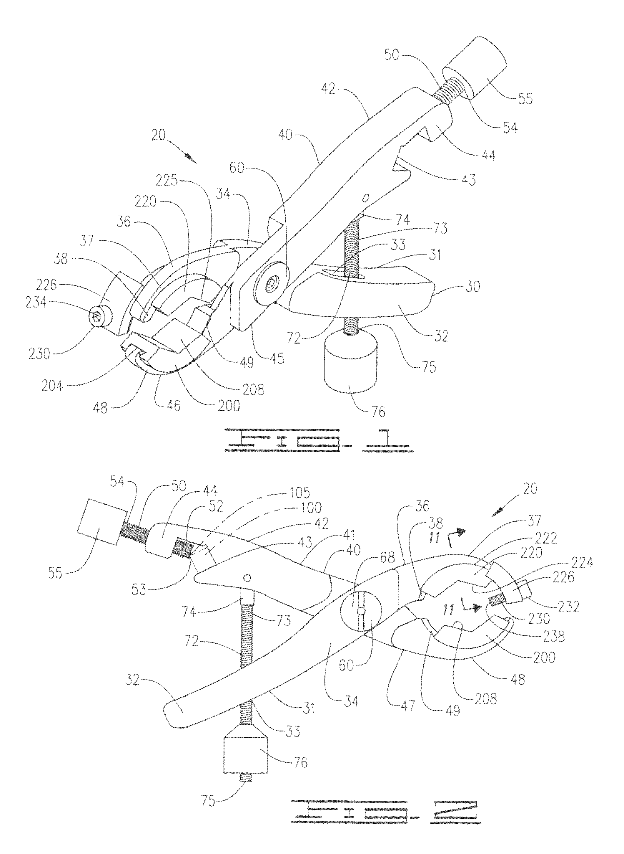
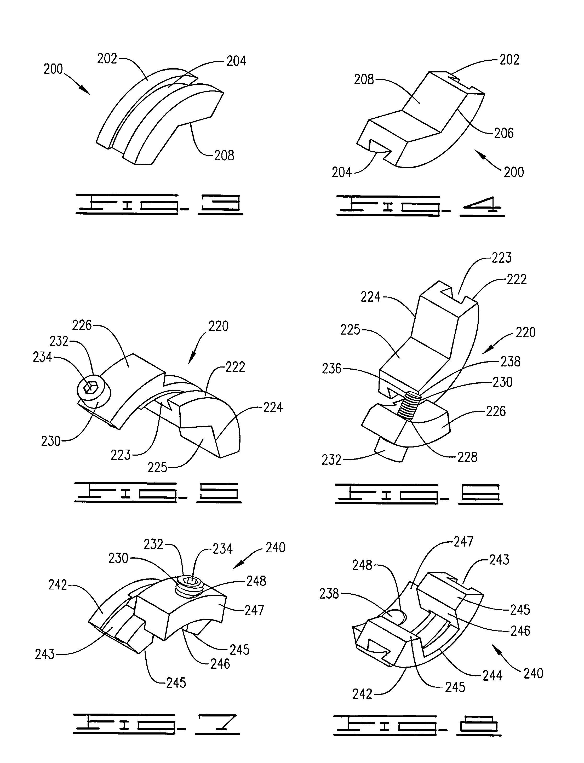
[0026]A bone reduction and plate clamp assembly 10 for the reduction of a fracture site B within a bone A and for the proper positioning and alignment of a bone plate C during the surgical repair of the bone, as shown and disclosed in FIGS. 1-12 of the drawings, provides a pair of bone clamps 20, a linear alignment bar 100, each bone clamp having at least two clamp members from a selection of at least one adjustable contact clamp member 200, at least one adjustable front projecting plate clamp member 220 or at least one adjustable central plate clamp member 240.

[0027]The linear alignment bar 100 is preferably a rigid bar having a square or other non-rounded profile, and would be a material that can withstand repeated use without deformation and also withstand repeated sterile cleansing for reuse. Most preferable of materials would be stainless steel, titanium or a non-porous plastic material. Using the square or non-rounded profile would reduce any potential rotation of the linear a...


PUM


Abstract

A pair of clamps are attached to a damaged bone one each side of a fracture site during a surgical reduction, one clamp on each side of the fracture site, after which the two clamps are slidably engaged to a single alignment bar, with the clamps then being adjusted to properly align the bone for a surgical attachment using a bone plate. Each clamp provides axially adjustable plate retainers which slides along a track on the end of each segment of the each clamp to position the retainers at a location where the bone plate is to be attached to the bone. Upon positioning, the bone plate is held against the bone with the bone still in proper alignment wherein screws anchor the plate to the bone, stabilizing the fracture site during the plate attachment procedure.

Description

CROSS REFERENCE TO RELATED APPLICATIONS[0001]None.I. BACKGROUND OF THE INVENTION[0002]1. Field of Invention[0003]A pair of clamps are attached to a damaged bone one each side of a fracture site during a surgical reduction, one clamp on each side of the fracture site, after which the two clamps are slidably engaged to a single alignment bar, with the clamps then being adjusted to properly align the bone for a surgical attachment using a bone plate. Each clamp provides axially adjustable plate retainers which slides along a track on the end of each segment of the each clamp to position the retainers at a location where the bone plate is to be attached to the bone. Upon positioning, the bone plate is held against the bone with the bone still in proper alignment wherein screws anchor the plate to the bone, stabilizing the fracture site during the plate attachment procedure.[0004]2. Description of Prior Art[0005]A preliminary review of prior art patents was conducted by the applicant whi...

Claims


Application Information

Patent Timeline
IPC IPC(8): A61B17/04
CPCA61B17/8019A61B17/8866A61B17/6466
Inventor JORDAN, CHRISTOPHER
Owner JORDAN CHRISTOPHER
Why Eureka
Try Eureka