Autofocus module

a technology of autofocus and module, applied in the field of lens structure, can solve the problems of inability to form conductive metal coatings, inability to reduce the production cost of conductive metal coatings, so as to increase the economic efficiency of manufacture and reduce processing costs

Active Publication Date: 2013-11-12
LARGAN PRECISION
View PDF5 Cites 6 Cited by
  • Summary
  • Abstract
  • Description
  • Claims
  • Application Information

AI Technical Summary

Benefits of technology

[0008]An objective of the present invention is to lower processing cost and to increase economic efficiency in manufacture.

Problems solved by technology

First, the conduction performance of the conductive metal coating is not stable.
Second, it is not easy to form the conductive metal coating.
Third, the conductive metal coating has a substantial part exposed outside, making the metal coating easily oxidized; or otherwise, the exposed metal coating may have unnecessary contact or connection with other components and thus wears out or peels off easily. Therefore, a need exists in the art to improve conventional autofocus modules.

Method used


Image

  • Autofocus module
  • Autofocus module
  • Autofocus module

Examples


Embodiment Construction

[0024]The present invention now will be described more fully hereinafter with reference to the accompanying drawings, in which preferred embodiments of the present invention are shown.

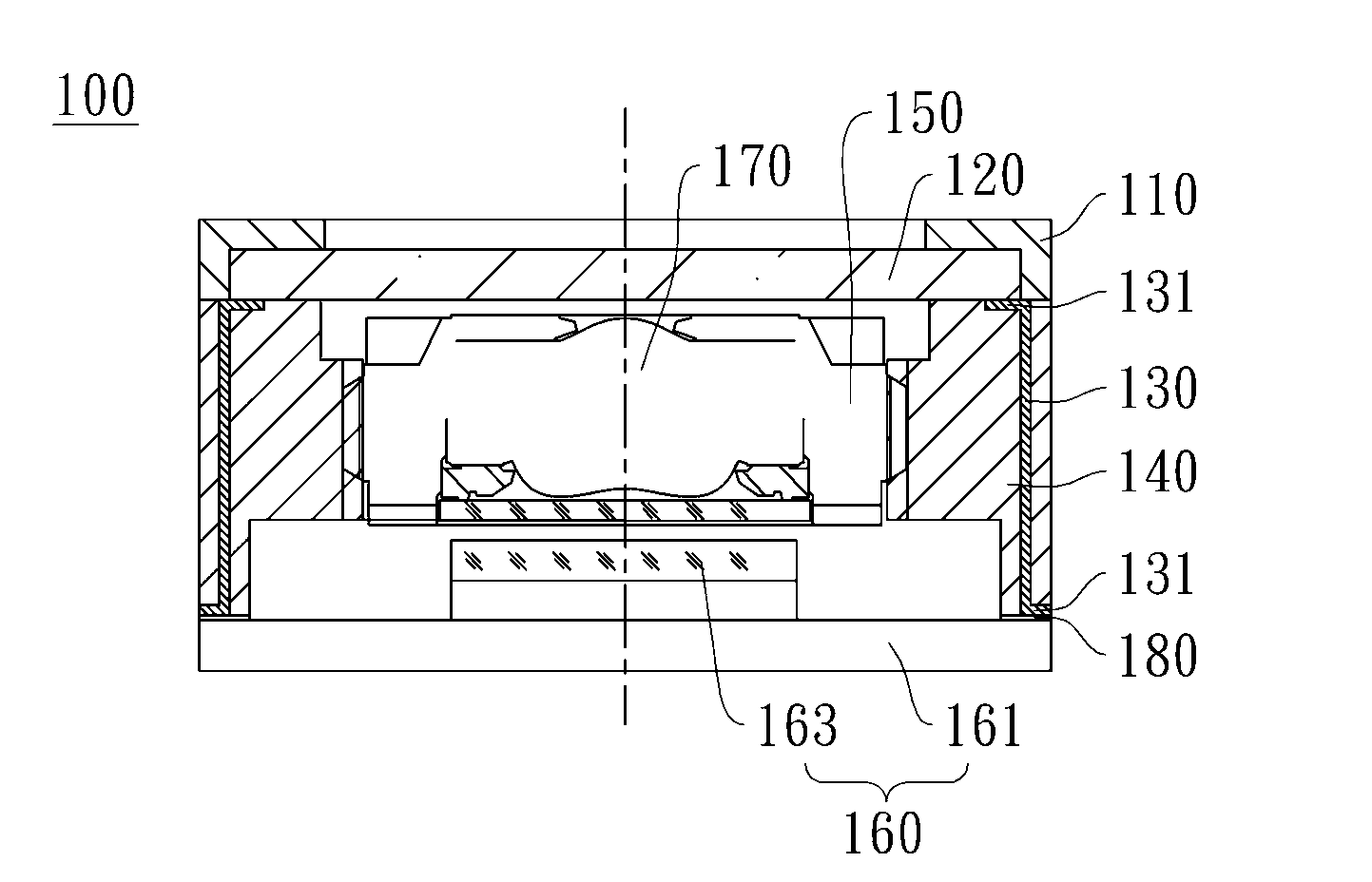
[0025]Referring to FIGS. 3A and 3B, FIG. 3A is a top view of an autofocus module according to a first embodiment of the present invention; FIG. 3B is a cross-sectional view of the autofocus module in FIG. 3A along line C-C in the same figure. In this embodiment, an autofocus module 100 of the present invention includes a focusing element supporting base 110, an electrical focusing element 120, at least one conductive element 130, a lens supporting base 140, a lens unit 150, and a sensor 160, wherein the lens unit 150 includes at least one lens element 170.

[0026]The focusing element supporting base 110 contains an accommodating space that runs from one end to the other. The electrical focusing element 120 may include a liquid lens, for example; preferably, the electrical focusing element 120 has a flat ...


PUM

PropertyMeasurementUnit
conductiveaaaaaaaaaa
shapeaaaaaaaaaa
sizeaaaaaaaaaa

Abstract

The present invention provides an autofocus module including: a supporting base, an electrical focusing element and an conductive element, wherein the supporting base at least accommodates one lens element, the electrical focusing element is disposed at one end of the supporting base so that the electrical focusing element and the lens element are positioned along a common optical lens, and the conductive element is embedded in the supporting base and connected to the electrical focusing element and an external power source respectively. The electrical focusing element obtains power through the conductive element, and by controlling the power magnitude supplied to the electrical focusing element, the focal length thereof can be changed accordingly, thereby carrying out the autofocus operation.

Description

CROSS-REFERENCE TO RELATED APPLICATION[0001]This non-provisional application claims priority under 35 U.S.C. §119(a) on Patent Application No. 099137910 filed in Taiwan, R.O.C. on Nov. 4, 2010, the entire contents of which are hereby incorporated by reference.BACKGROUND OF THE INVENTION[0002]1. Field of the Invention[0003]The present invention relates to a lens structure, and more particularly, to an autofocus module.[0004]2. Description of the Prior Art[0005]With the rapid development of consumer electronics, there is an ever increasing need to keep the products as compact as possible, and accordingly, the internal product components are required to have their size minimized so as to make the whole product more compact and portable. Also, there is an increasing need for imaging products featuring variable focal length, which drives the demand for imaging products with a motor-driven autofocus mechanism. An example of a conventional autofocus module is described below. The autofocus...

Claims


Application Information

Patent Timeline
Patent Type & Authority Patents(United States)
IPC IPC(8): G02B7/02G02B15/14G02F1/29G03B13/00G03B13/18
CPCG02B7/023G02B7/08
Inventor HUANG, CHEN-YITSENG, TE-SHENGHSU, WEN-HUNG
Owner LARGAN PRECISION
Why Eureka
Try Eureka