Method and system for providing a magnetic transducer having a high moment bilayer magnetic seed layer for a trailing shield

a high-moment bilayer, trailing shield technology, applied in the direction of instruments, data recording, metal sheet core heads, etc., can solve the problems of b>10/b> being subject to error, conventional trailing shields may not be able to adequately shield poles,

Active Publication Date: 2013-11-12
WESTERN DIGITAL TECH INC
View PDF19 Cites 193 Cited by
  • Summary
  • Abstract
  • Description
  • Claims
  • Application Information

AI Technical Summary

Problems solved by technology

Although the conventional magnetic recording transducer 10 functions, there are drawbacks particularly as the conventional transducer 10 is desired to be scaled to higher recording densities.
The conventional trailing shield may, therefore, be unable to adequately shield the pole 14 from the media and vice versa.
Thus, a disk drive using the conventional transducer 10 may be subject to error.

Method used


Image

  • Method and system for providing a magnetic transducer having a high moment bilayer magnetic seed layer for a trailing shield
  • Method and system for providing a magnetic transducer having a high moment bilayer magnetic seed layer for a trailing shield
  • Method and system for providing a magnetic transducer having a high moment bilayer magnetic seed layer for a trailing shield

Examples


Embodiment Construction

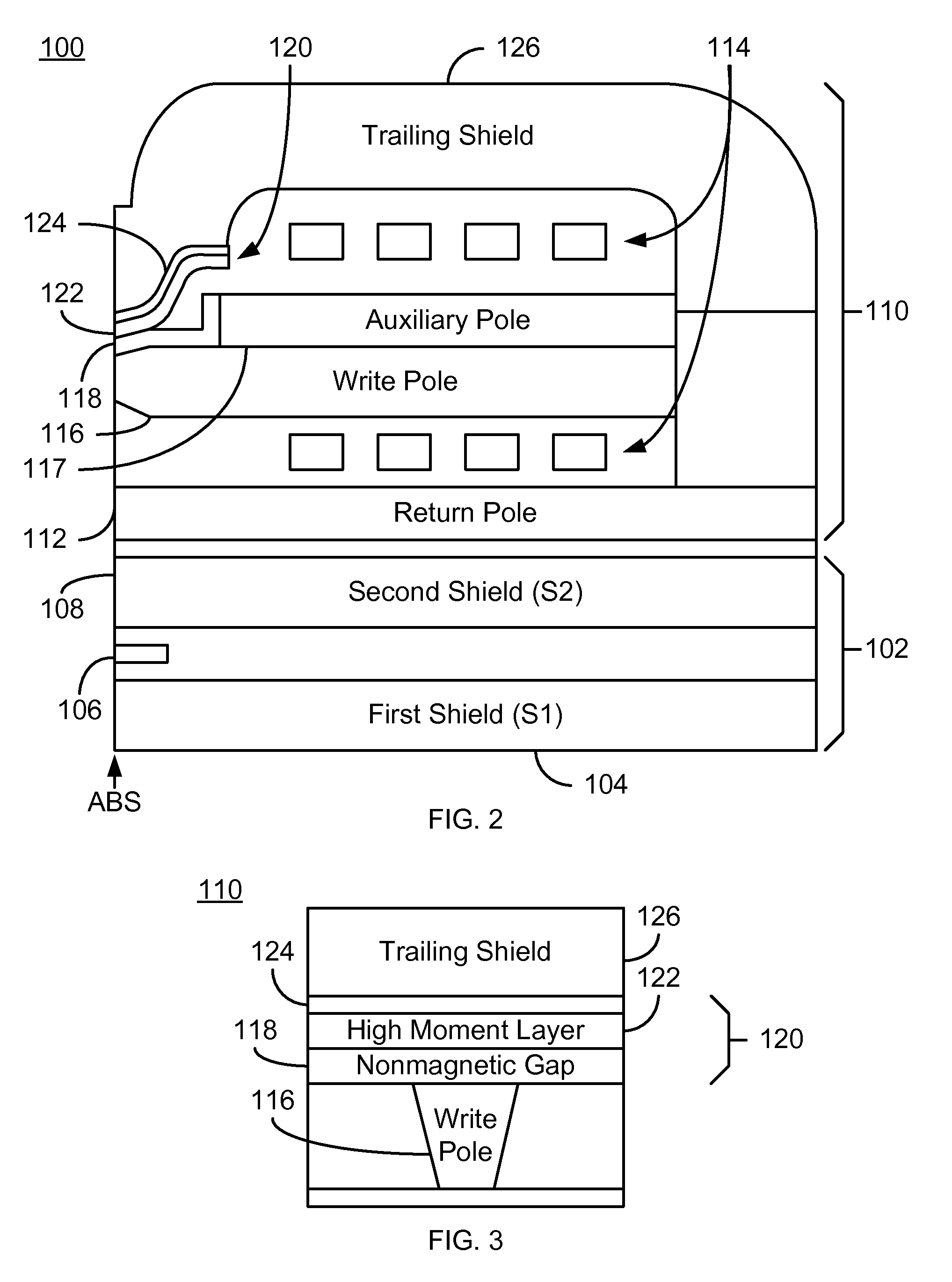
[0011]FIGS. 2-3 depict a magnetic head 100. A side view of the head is depicted in FIG. 2, while an ABS view of a portion of the head is shown in FIG. 3. FIGS. 2 and 3 are not to scale and not all components of the magnetic head 100 are shown. The magnetic head 100 is a merged head that includes a magnetic write transducer 110 and a magnetic read transducer 102. In other embodiments, the read transducer 102 and write transducer 110 may also be in separate heads. The magnetic head 100 resides on a slider and is typically one of many magnetic heads in a disk drive and used to write to and read from a media (not shown).

[0012]The read transducer 102 includes shields 104 and 108 as well as sensor 106. The sensor 106 may be used to read data from a media (not shown). The shields 104 and 108 may be a soft magnetic material, such as NiFe. The shields 104 and 108 magnetically isolate the sensor 106 from bits not being read during operation of the transducer 102. The sensor 106 is sensitive t...


PUM

PropertyMeasurementUnit
thicknessaaaaaaaaaa
thicknessaaaaaaaaaa
heightaaaaaaaaaa

Abstract

A method and system for providing a magnetic read transducer is described. The magnetic recording transducer includes a write pole, a nonmagnetic gap, a magnetic seed layer, a trailing shield and coil(s) that energize the write pole. The write pole is configured to write to a media. The nonmagnetic gap is between the write pole and the magnetic seed layer. The magnetic seed layer includes a high moment layer and a magnetic buffer layer. The high moment layer is between the nonmagnetic gap and the magnetic buffer layer. The high moment layer has a saturation magnetization greater than 2.3 T and a first corrosion potential. The magnetic buffer layer has a second corrosion potential less than the first corrosion potential. The magnetic seed layer is between the trailing shield and the nonmagnetic gap layer. The magnetic buffer layer is between the trailing shield and the high moment layer.

Description

BACKGROUND[0001]FIG. 1 depicts a portion of a conventional magnetic transducer 10, such as a conventional write transducer, as viewed from the air-bearing surface (ABS). The conventional transducer 10 includes a nonmagnetic underlayer 12 that may reside on a bottom shield, a conventional write pole 14, a conventional write gap 16, a conventional NiCr seed layer 18 a conventional magnetic seed layer 20, and a conventional trailing shield 22. The conventional write gap 16 is nonmagnetic, as is the conventional NiCr seed layer 18. The conventional magnetic seed layer 20 typically consists of Co40Ni5Fe55. The conventional trailing shield typically has a high permeability and a high saturation magnetization.[0002]Although the conventional magnetic recording transducer 10 functions, there are drawbacks particularly as the conventional transducer 10 is desired to be scaled to higher recording densities. For example, the conventional trailing shield 22 is also scaled to smaller dimensions. ...

Claims


Application Information

Patent Timeline
Patent Type & Authority Patents(United States)
IPC IPC(8): G11B5/147
CPCG11B5/1278G11B5/3116G11B5/315
Inventor YU, CHENGTAO R.HAN, DEHUAHONG, YINGLIU, FENGZHANG, BOPAN, TAO
Owner WESTERN DIGITAL TECH INC
Why Eureka
Try Eureka