Engine induction system

Active Publication Date: 2013-11-19
AERISTECH
View PDF81 Cites 32 Cited by
  • Summary
  • Abstract
  • Description
  • Claims
  • Application Information

AI Technical Summary

Benefits of technology

The invention decouples the turbine and compressor in an engine, which allows for better control of the compressor based on driver requirements. This results in improved responsiveness, independent of operational limitations of the turbine. The turbine can also be aerodynamically optimized for better performance. Additionally, the invention increases efficiency by allowing the turbine to recover more energy in varying states, resulting in improved performance compared to conventional arrangements.

Problems solved by technology

However turbine design is not flexible enough to allow suitable operation of the turbocharger over the entire spectrum of engine speeds and so operation at low engine speeds is typically sacrificed in favour of improved operation of the turbocharger at greater speeds.
A further problem associated with conventional turbochargers is the boost threshold.
At low engine speeds, the exhaust gas flow may be insufficient to attain the required turbine flow rate and thus a conventional turbocharger is often unable to meet acceleration demands placed on the system until a threshold engine speed has been reached.
This need for a sufficient engine exhaust pressure to operate the turbocharger results in the turbocharger being idle or ineffective at low speeds.
Given the inherent difficulties in designing a system for transient use, a turbocharger tends to be designed around ‘average’ operational conditions.
Furthermore the turbocharger inertia also causes a delay in response to variations in engine output, often referred to as turbo lag, which compromises the driveability of a turbocharged vehicle.
Turbo lag may also be attributed to insufficient exhaust gas being available at the instant an acceleration demand is made by the driver.
Once the turbocharger is operational, the turbine inertia also causes the turbocharger to recover energy which is potentially unwanted by the driver upon a deceleration of the vehicle.
This results in complex systems which are prone to reliability issues and for which operational efficiency is reduced.
A supercharger responds almost instantaneously to driver inputs, improving driveability even at low engine speeds, albeit at the detriment to engine efficiency.
Whilst such an arrangement, does improve driveability to some extent, it does not adequately address the problem of the turbocharger generating unwanted energy during deceleration.
Thus, as is common with turbochargers, a wastegate must be provided to allow exhaust gas to bypass the turbocharger when necessary, causing potentially useful exhaust pressure to be lost.
The holding back of the turbocharger to suit engine conditions results in the turbocharger efficiency being dictated by the requirements placed upon the compressor by the driver, ultimately capping the available efficiency savings.

Method used


Image

  • Engine induction system
  • Engine induction system
  • Engine induction system

Examples


Embodiment Construction

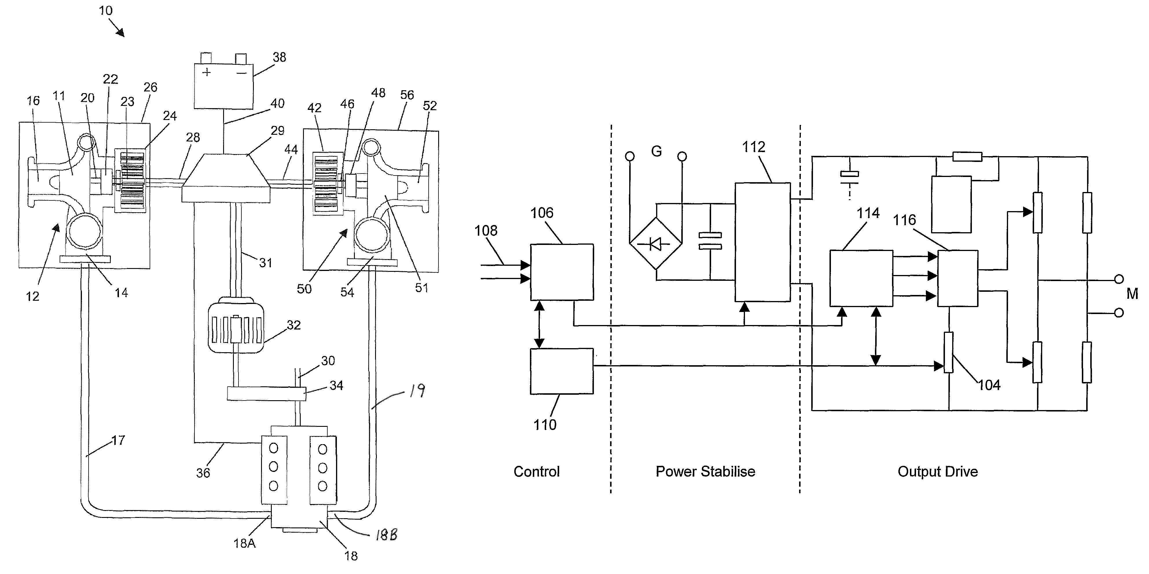
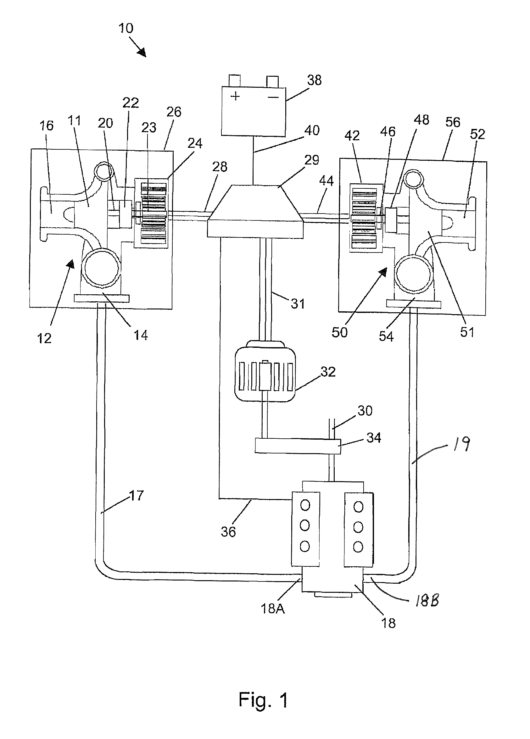
[0044]Turning firstly to FIG. 1, there is shown the physical connections between the basic components according to one embodiment of the present invention. It will be appreciated that the system of the present invention is typically suited for use in conjunction with internal combustion engines for road vehicles, although the present invention can be applied to other applications in which there is a transfer of compression work between two gas streams.

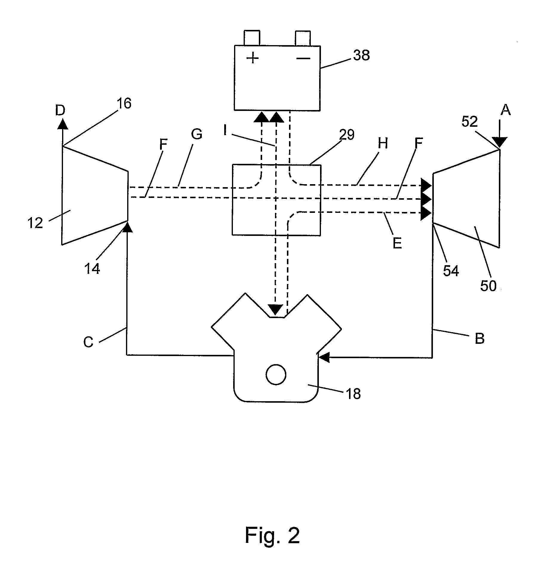
[0045]The basic system 10 shown in FIG. 1 comprises a turbine 12 having a turbine wheel 11, a tangential gas inlet 14 and an axial gas outlet 16. The inlet 14 is connected to the exhaust 18A of engine 18 by ducting 17 in a conventional manner, such that the flow of combustion gasses exiting the engine cylinders drives the turbine 12.

[0046]A variable frequency AC generator 24 is connected to the turbine output shaft 20. The output torque of the turbine drives the three-phase generator rotor. Mechanical linkage in the form of gearing 22 ...


PUM


Abstract

A forced induction system for an engine comprising a compressor for increasing the pressure of gas into the engine and a turbine arranged to be driven by engine exhaust gas. The system further comprises a generator and an electric motor. The generator is arranged to be driven by the turbine and the motor is arranged to drive the compressor, wherein the generator and motor are electrically connected. The system comprises electrical control means arranged to receive the electrical signal output by said generator during operation and to apply an AC control signal to said electric motor whereby the compressor is driven at least in part by an output torque of the turbine via the electrical connection therebetween.

Description

CROSS-REFERENCE TO RELATED APPLICATIONS[0001]This application is the U.S. national stage application of International Application PCT / GB2007 / 004339 filed Nov. 14, 2007, which international application was published on Jun. 12, 2008, as International Publication WO 2008 / 068453 in the English language. The International Application claims priority of GB Patent Application 0624599.7, filed Dec. 9, 2006.BACKGROUND OF THE INVENTION[0002]The present invention relates to forced air induction systems for engines and more particularly, although not exclusively, to the use of such systems for improving the performance of an internal combustion engine.[0003]Turbochargers and mechanical superchargers are well known forms of forced air induction systems. Both systems operate by driving a compressor so as to increase the air pressure into an internal combustion engine in order to improve performance. The source of the driving force for the compressor has a significant impact on the overall perfor...

Claims


Application Information

Patent Timeline
IPC IPC(8): F02B33/44H02P27/04F01D15/10H02P1/04H02K7/14F04B23/00
CPCF01D15/10F02B37/10F02B39/10F02C7/36F02D41/0007Y02T10/144F05D2220/40F01N5/04Y02T10/12F02B37/14F02D23/00F02D43/04
Inventor RICHARDS, BRYN
Owner AERISTECH
Why Eureka
Try Eureka