

Anti-ligature door hardware
a technology of anti-ligature and door hardware, which is applied in the direction of wing knobs, keyhole guards, mechanical control devices, etc., can solve the problems of reducing the opportunity, reducing the privacy and security of the entire room, and reducing the opportunity
- Summary
- Abstract
- Description
- Claims
- Application Information
AI Technical Summary
Benefits of technology
Problems solved by technology
Method used
Image

Examples
Embodiment Construction
[0017]The present teachings are described more fully hereinafter with reference to the accompanying drawings, in which the present embodiments are shown. The following description is presented for illustrative purposes only and the present teachings should not be limited to these embodiments.
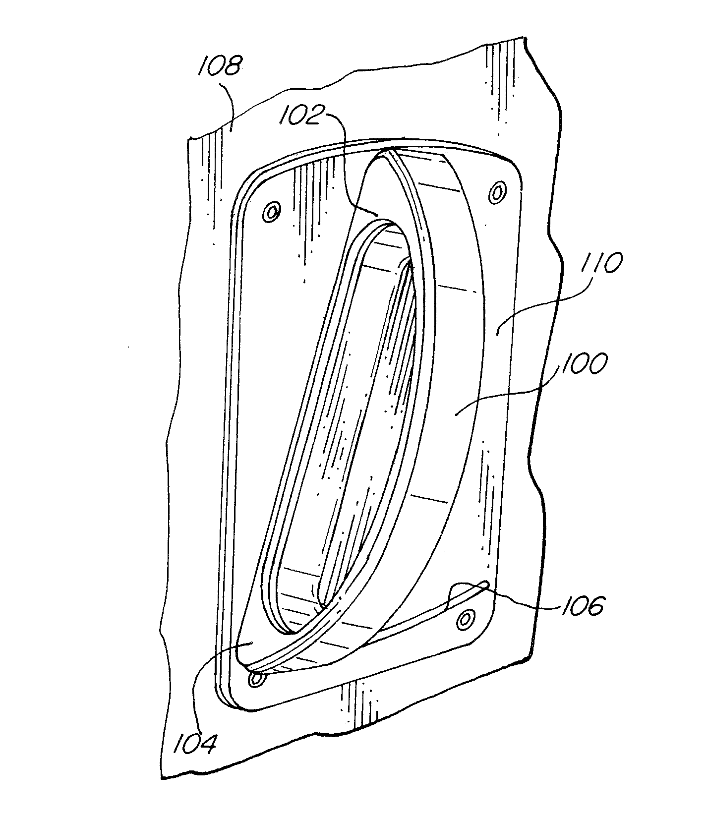
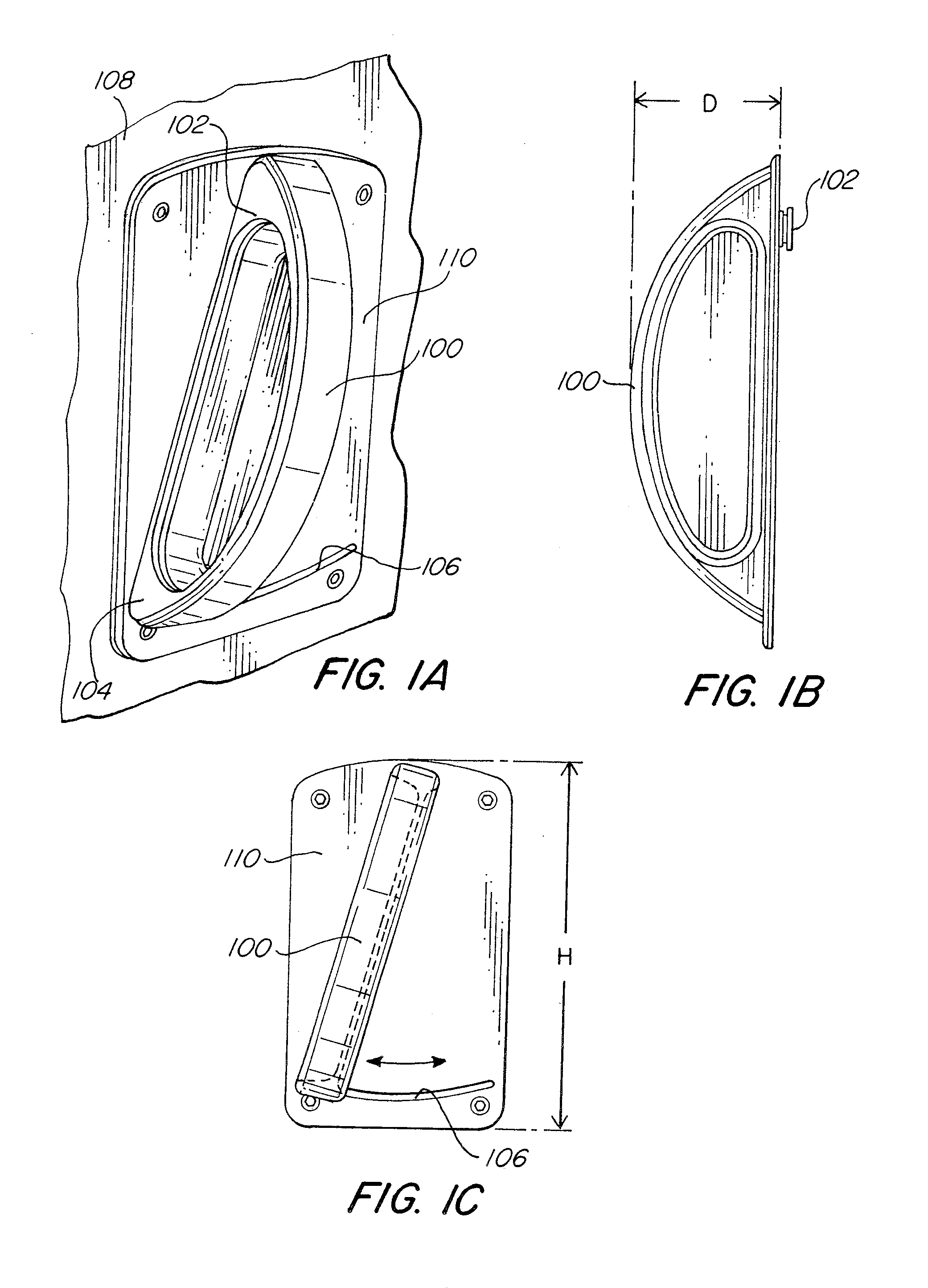
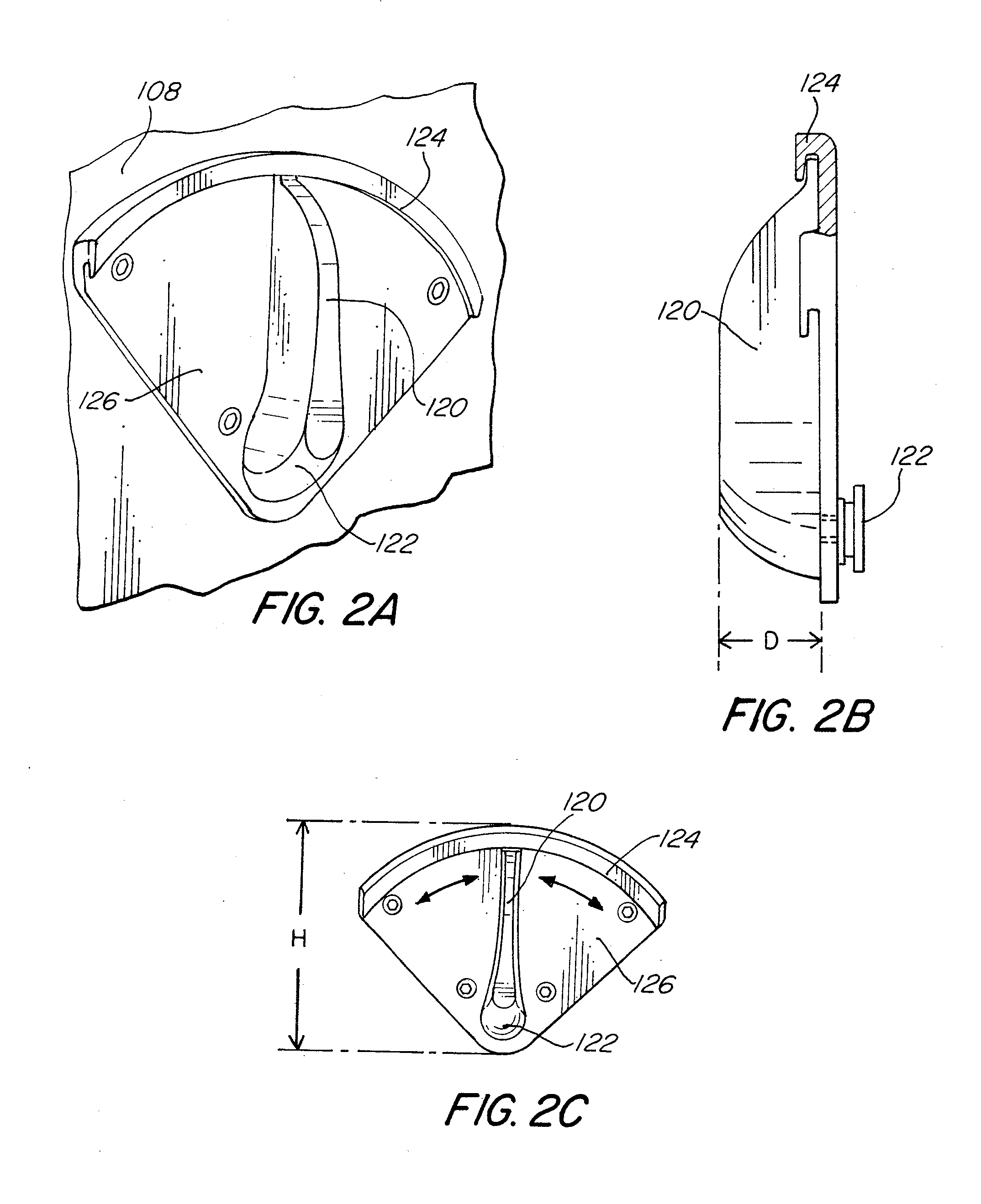
[0018]In one embodiment of the door hardware, an anti-ligature door handle according to the present teachings comprises an elongated member, which may be crescent-shaped, and which is tapered to thwart its use as a means for affixing or hanging a ligature. The door handle may have a toe and be in pivotal connection with a plate member which has a toe track for receiving the toe of the elongated member. So constructed, the door handle both inhibits suicide attempts and yet remains easily operable, which may benefit, for example, those with disabilities.
[0019]Referring now to FIGS. 1A, 1B and 1C, shown are illustrations of one embodiment of a door handle 100 according to the present teachings. As ...
PUM
 Abstract
Description
Claims
Application Information