
Apparatus for applying a pumpable material to a rail head

a technology of friction modification material and rail head, which is applied in the direction of rail lubrication, rail wetting/lubrication, machines/engines, etc., can solve the problems of less than satisfactory prior art devices

Active Publication Date: 2013-11-19
LINCOLN INDUSTRIES CORP
View PDF39 Cites 15 Cited by
  • Summary
  • Abstract
  • Description
  • Claims
  • Application Information

AI Technical Summary

Problems solved by technology

However, such prior art devices have been less than satisfactory for any number of reasons.

Method used


Image

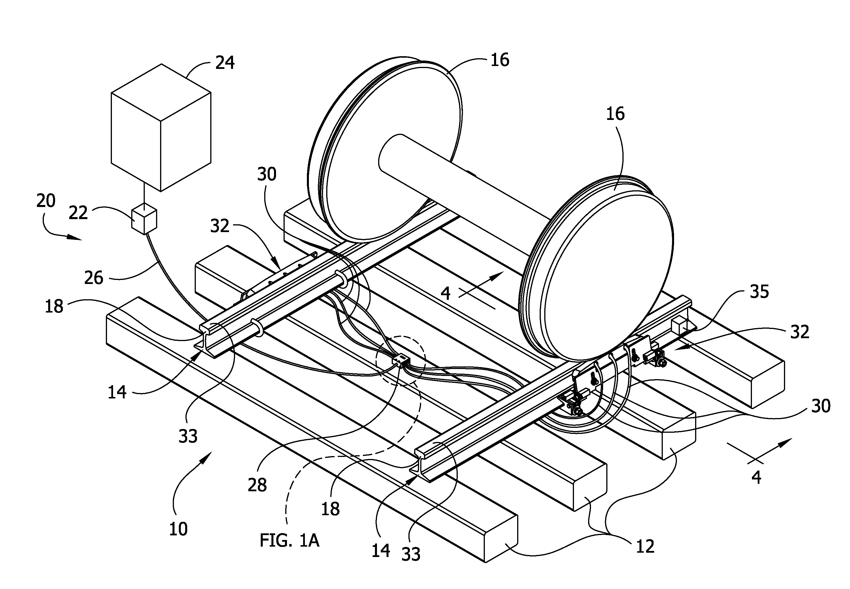
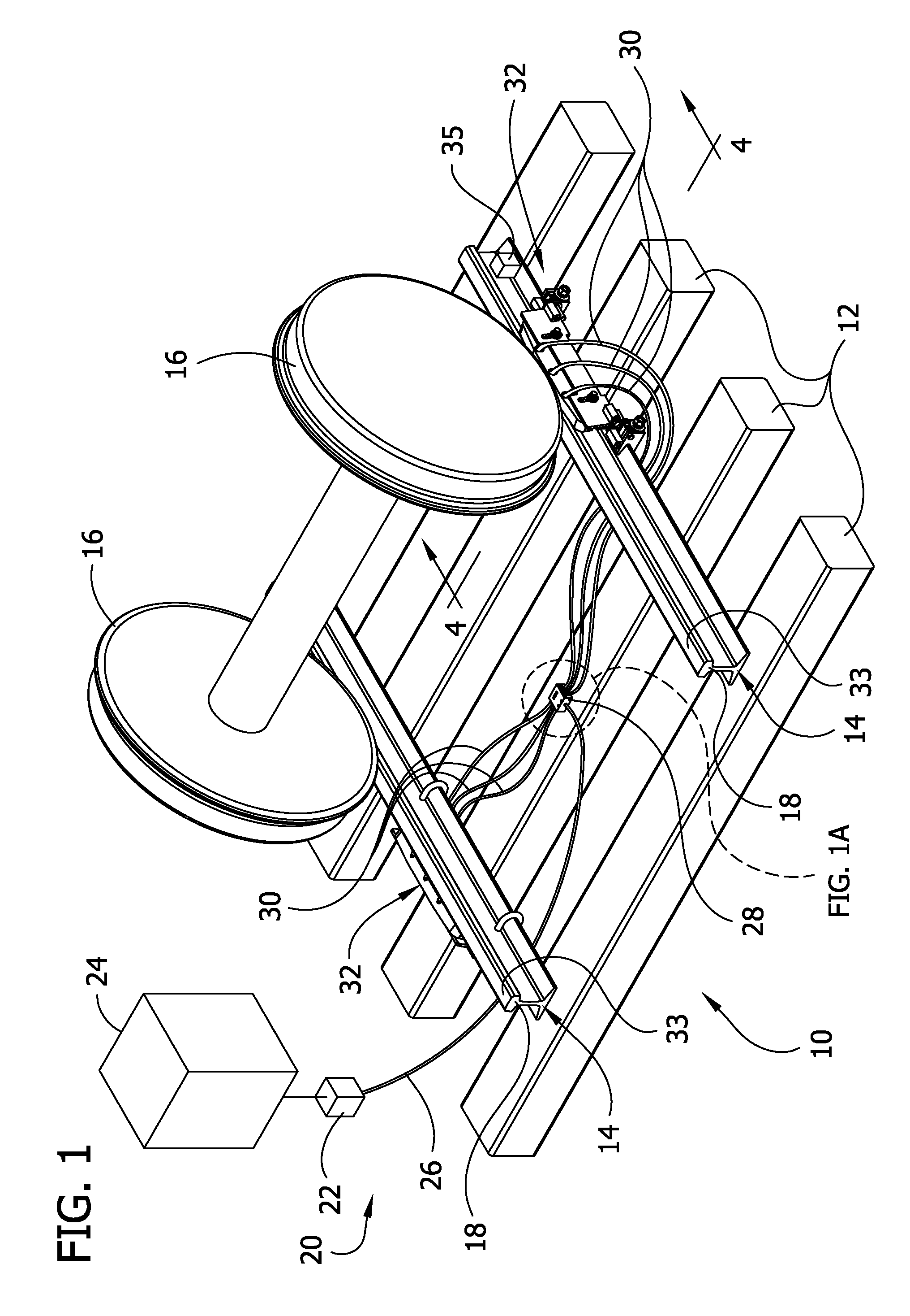
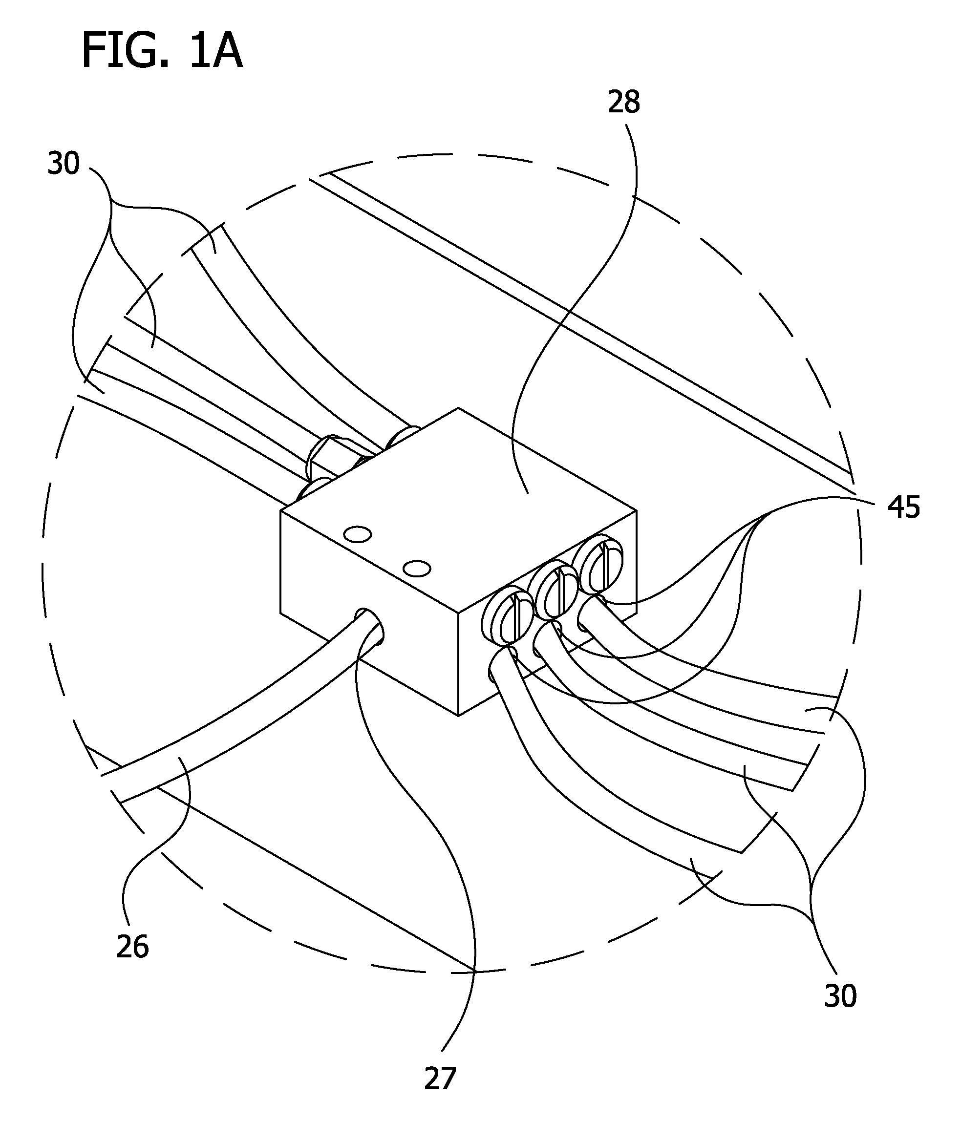
  • Apparatus for applying a pumpable material to a rail head
  • Apparatus for applying a pumpable material to a rail head
  • Apparatus for applying a pumpable material to a rail head

Examples


second embodiment

[0046]FIGS. 12-17 show the present invention, generally designated 201. The apparatus of this embodiment is similar to the apparatus of the previous embodiment and corresponding parts are indicated by corresponding reference numbers with the addition of a prime (′) designation. As best illustrated in FIGS. 13 and 14, when the applicator bar 42′ is in its working position, the inboard face 58′ of the bar contacts the rail head to form a metal-on-metal hard seal 205 which extends lengthwise of the rail head. The hard seal 205 functions to inhibit the leakage of friction modifying material down from the rail head 18 and eliminates the need for conventional “soft” seals, i.e., seals of rubber or other relatively soft material, which tend to wear down over time and need to be replaced. Desirably, the contact area 205 between the inboard metal face 58′ of the applicator bar 42′ and the rail head 18 extends substantially the full length of the applicator bar. In the embodiment shown in the...

first embodiment

[0050]In use, the applicator assembly of apparatus 201 is secured to a rail by the securing device 41′ previously described, or some other suitable securing device. The mounting plate 80′ and applicator bar 42′ are then pivoted to the working position shown in FIGS. 13 and 14 in which the applicator bar contacts the rail head 18 to make the hard seal 205. The applicator bar 42′ is locked in this position, as described previously with respect to the The spring mechanisms 221 urge the bar 42′ against the rail head 18 to maintain the hard seal 205 over time when gaps might otherwise form between the bar and the rail due to vibration, loosening of parts, wear, etc. In the event a wheel 16 of a train contacts the applicator bar 42′, the bar will move down against the bias of the springs 76′ from a raised position to a depressed position to avoid damage to the bar, as described earlier. When the wheel moves out of contact with the bar 42′, the bar returns to its raised position. During t...


PUM


Abstract

An applicator assembly for delivery of a pumpable material to a top surface of a rail head of rail includes an applicator body having an orifice for delivery of the pumpable material to the top surface of the rail. The body is resiliently yieldable to permit the applicator body to move from a raised position, in which the orifice is positioned for delivering the pumpable material to the top surface of the rail head, to a depressed position in the event the applicator is contacted by a train wheel. The applicator body thereafter returns to the raised position. The applicator body is mounted for movement between a working position in which the applicator body is closely adjacent the rail head and a rail-service position in which the applicator body is remote from the rail head. When the applicator body is in its working position, a metal portion of the applicator body contacts the rail head to form a metal-on-metal hard seal extending lengthwise of the rail head for inhibiting leakage of the pumpable material from the top of the rail head. The applicator assembly is free of any non-metal seals for sealing against such leakage.

Description

CROSS REFERENCE TO RELATED APPLICATION[0001]This is a continuation-in-part of co-assigned U.S. patent application Ser. No. 11 / 769,057, filed Jun. 27, 2007.FIELD OF THE INVENTION[0002]This invention relates to an apparatus for applying pumpable material to a rail head of a rail, and more particularly to an apparatus for applying a friction modifying material to a rail head of a railroad rail.BACKGROUND OF THE INVENTION[0003]It is common practice to apply lubricants (e.g., grease) and other friction modifying materials onto railroad rails, such as to the tops or sides of the rails at or near curves, turnouts, switches and other locations where such materials are needed or desired. As applied to the rails, such materials either reduce or increase the friction where necessary to improve train performance and reduce wear on both the rails and the train wheels.[0004]In the case of a friction modifying material that controls the friction between the train wheel and the rail, the convention...

Claims


Application Information

Patent Timeline
Patent Type & Authority Patents(United States)
IPC IPC(8): B61K3/00
CPCB61K3/00
Inventor HOLLAND, CHRISTOPHER D.
Owner LINCOLN INDUSTRIES CORP
Learn More