Connector

a technology of connecting rods and connectors, applied in the direction of coupling contact members, coupling device connections, coupling parts engagement/disengagement, etc., can solve the problem that the connecting rod cannot be fitted into the mating connector, and achieve the effect of preventing clashing, reducing the connection reliability between the terminal and the terminal of the mating connector, and preventing the reduction of the connection reliability

Active Publication Date: 2013-11-19
YAZAKI CORP
View PDF18 Cites 27 Cited by
  • Summary
  • Abstract
  • Description
  • Claims
  • Application Information

AI Technical Summary

Benefits of technology

[0051]According to the invention claimed in claim 1, the terminal is provided with the first electric connecting part received and held in the inner housing, and electrically connected to a mating connector, the second electric connecting part disposed further away from the mating connector than the first electric connecting part, and the coupling part made of conductive material, having flexibility or elasticity, and movably coupling and electrically connecting the first electric connecting part and the second connecting part, and the outer housing is provided with the receiving part movably receiving the inner housing receiving the first electric connecting part, and the fixing part to which the second electric connecting part is fixed. Therefore, when a position gap between the terminal and the terminal of the mating connector is generated, the inner housing supporting the first electric connecting part is moved in the receiving part so as to electrically connect the first electric connecting part and the terminal of the mating connector, thereby absorbs the position gap. Further, even when the inner housing and the first electric connecting part are moved in this way, the second electric connecting part is fixed to the fixing part, and not moved. Therefore, the connection reliability between the second electric connecting part and a member electrically connected to the second electric connecting part is prevented from being reduced. Further, when the first electric connecting part is moved in this way, the flexible or elastic coupling part is deformed. Therefore, a distortion between the first and second electric connecting parts is prevented from being generated. Further, when a vibration is applied to this connector, the coupling part is deformed to absorb the vibration. Therefore, the connection reliability between the terminal and the terminal of the mating connector is prevented from being reduced. Therefore, a connector able to be surely fitted with the mating connector by absorbing a position gap generated between the terminal and a terminal of the mating connector when fitting with the mating connector can be provided.
[0052]According to the invention claimed in claim 2, because the coupling part is composed of a braided wire, the coupling part can be deformed in all directions. Therefore, a connector able to be further surely fitted with the mating connector by absorbing a position gap generated between the terminal and a terminal of the mating connector in all directions when fitting with the mating connector can be provided.
[0053]According to the invention claimed in claim 3, the coupling part is made by pressing a metal plate, formed elastically deformable in all directions, and composed of a first circular part attached to the first electric connecting part, a second circular part attached to the second electric connecting part, and a plurality of bow-shaped parts of which one end is continued to the first circular part, and the other end is continued to the second circular part and formed in a band shape, and of which intermediate part between the first and second circular parts is bend in a bow shape. Further, because the coupling part is elastically deformed, the coupling part couples the first and second electric connecting parts movably in all directions. Therefore, a connector able to be further surely fitted with the mating connector by absorbing a position gap generated between the terminal and a terminal of the mating connector in all directions when fitting with the mating connector can be provided.
[0054]According to the invention claimed in claim 4, because the coupling part is composed of a coil spring, the coupling part can be deformed in all directions. Therefore, a connector able to be further surely fitted with the mating connector by absorbing a position gap generated between the terminal and a terminal of the mating connector in all directions when fitting with the mating connector can be provided.
[0055]According to the invention claimed in claim 5, the connector further includes a biasing member interposed between the fixing part and the inner housing, and configured to bias the inner housing toward the mating connector. Therefore, when the mating connector collides with the inner housing while fitting with the connector, the inner housing is once moved toward the fixing part, and then pushed back toward the mating connector due to the elastic restoring force of the biasing member. Therefore, the inner housing is prevented from clashing with the fixing part and from being damaged. Further, when a vibration is applied to this connector, the biasing member is elastically deformed to absorb the vibration. Therefore, the connection reliability between the terminal and the terminal of the mating connector is prevented from being reduced. Therefore, a connector able to be surely fitted with the mating connector by absorbing a position gap generated between the terminal and the terminal of the mating connector when fitting with the mating connector, and able to prevent the connector from being damaged by an impact generated when fitting with the mating connector can be provided.
[0056]According to the invention claimed in claim 6, because the biasing member is composed of a coil spring, a connector able to be surely fitted with the mating connector by absorbing a position gap generated between the terminal and the terminal of the mating connector when fitting with the mating connector, and able to prevent the connector from being damaged by an impact generated when fitting with the mating connector can be provided.

Problems solved by technology

In the aforementioned connector, sometimes a position gap is generated between the terminal of the connector and the terminal of the mating connector, so that the connector cannot be fitted into the mating connector.

Method used


Image

  • Connector
  • Connector
  • Connector

Examples


first embodiment

(First Embodiment)

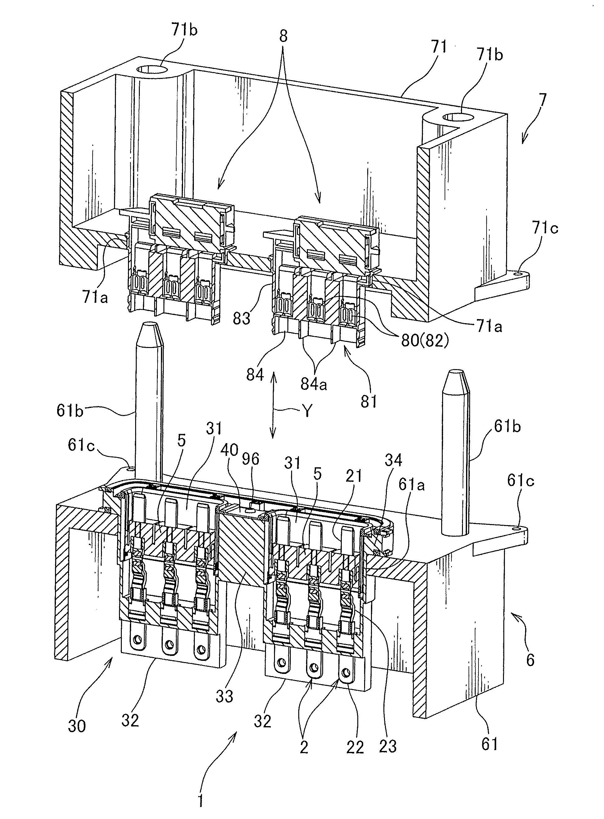
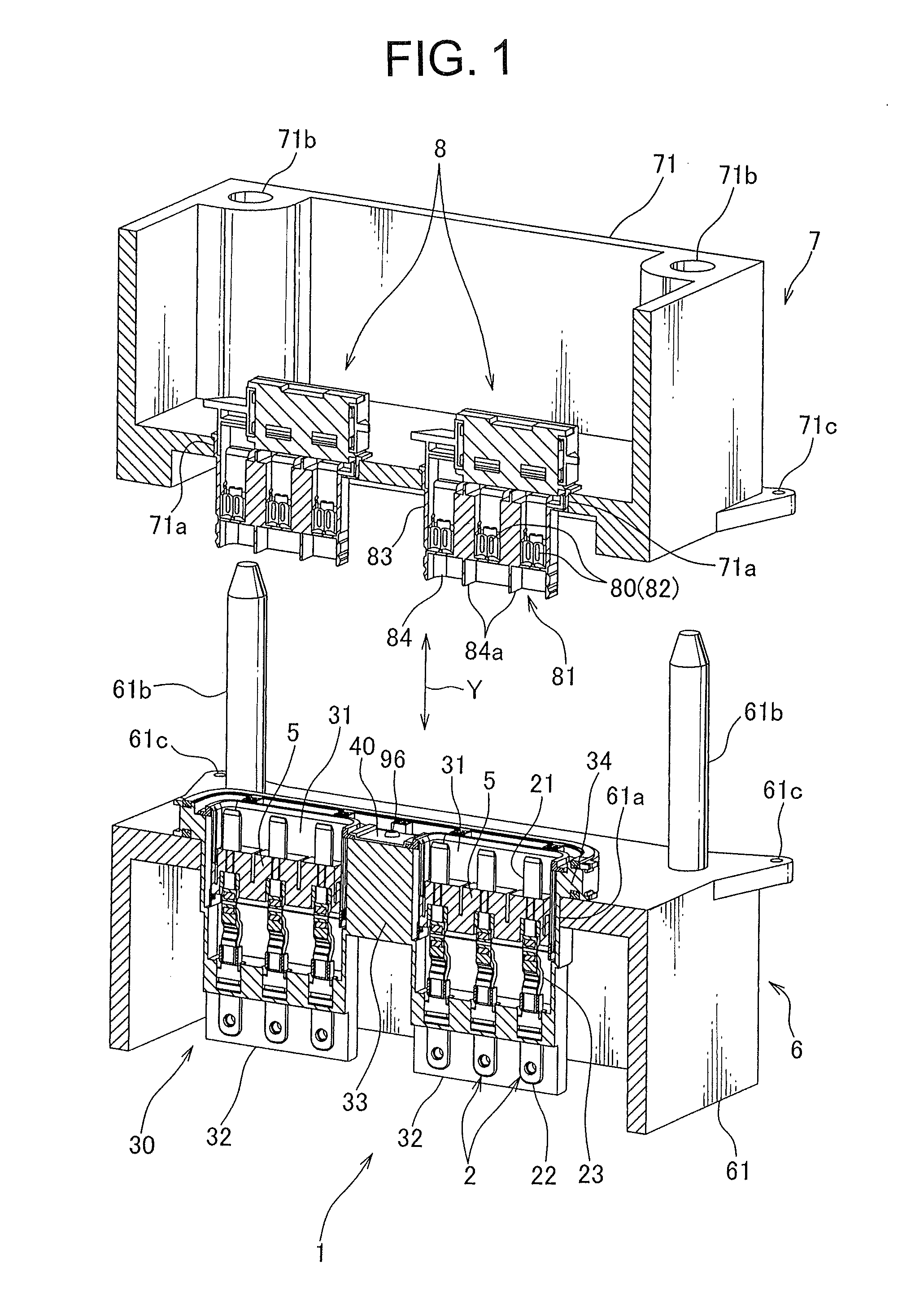
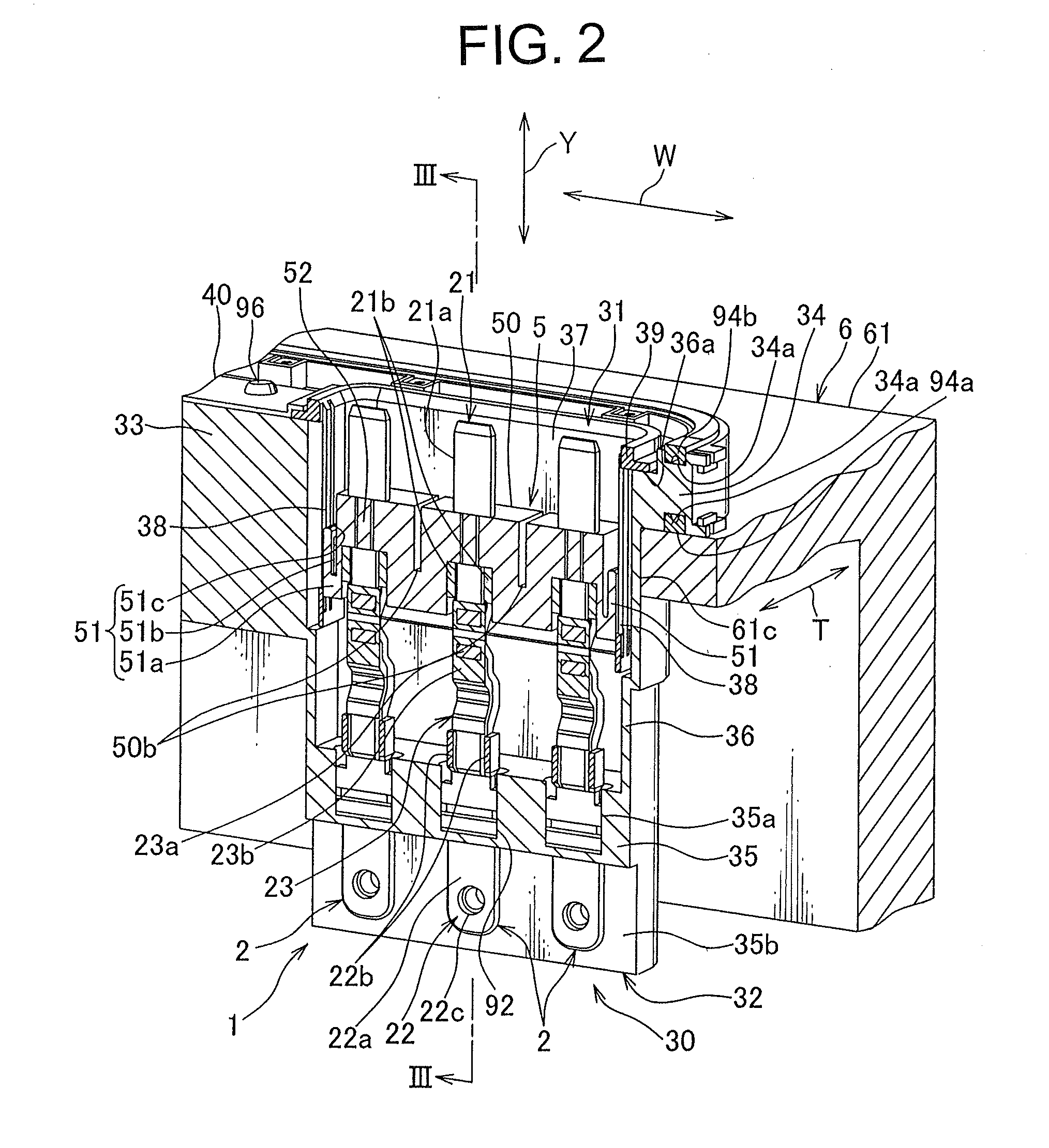
[0088]A connector according to a first embodiment of the present invention will be explained with reference to FIGS. 1 to 3.

[0089]As shown in FIG. 1, a pair of connectors 1 is attached to a case 61 of a motor 6 mounted on an electric vehicle or a hybrid vehicle, and fitted with, namely, electrically connected to a pair of mating connectors 8 attached to a case 71 of an ECU (Electric Control Unit) 7. Namely, when the ECU 7 is mounted on the motor 6, the pair of connectors 1 is directly connected to the pair of mating connectors 8 integrally provided with the ECU 7.

[0090]Further, the pair of mating connectors 8 is respectively attached to a pair of connector receiving holes 71a provided on the case 71 of the ECU 7. The connector receiving hole 71a penetrates an outer wall of the case 71, and is formed in a shape following an outer surface of a housing main body 83 of a later-described housing 81 of the mating connector 8. Further, a positioning hole 71b into which a ...

second embodiment

(Second Embodiment)

[0130]A connector 101 according to a second embodiment of the present invention will be explained with reference to FIGS. 4 to 7.

[0131]As shown in FIG. 5, the connector 101 is fitted with a mating connector 111 to be electrically connected to the mating connector 111. Further, the mating connector 111 includes: a tubular housing 113; and a terminal 112 received in the housing 113. The terminal 112 is made of a metallic plate, and formed in a tubular shape, namely, a female type. Further, a plurality of spring pieces 112a elastically deformable along a radial direction of the terminal 112 is provided on the terminal 112 by forming a plurality of slits on an outer wall of the terminal 112. These spring pieces 112a elastically contact a first electric connecting part 121 of a later-described terminal 102 of the connector 101, and press the first electric connecting part 121 inward.

[0132]Further, an arrow Y shown in FIGS. 4 to 7 indicates a fitting direction of the ma...

third embodiment

(Third Embodiment)

[0154]A connector 201 according to a third embodiment of the present invention will be explained with reference to FIGS. 8 and 9.

[0155]The connector 201 is fitted with a mating connector (not shown) and electrically connected to the mating connector. Further, an arrow Y of FIGS. 8 and 9 indicates a fitting direction between the connector 201 and the mating connector, and an arrow X indicates a direction perpendicular to the fitting direction. As shown in FIGS. 8 and 9, the connector 201 includes: a terminal 202; an inner housing 204 receiving and holding a later-described first electric connecting part 221 of the terminal 202; and an outer housing203 receiving the terminal 202 and the inner housing 204.

[0156]The terminal 202 is provided with the first electric connecting part 221 for electrically connected to the terminal of the mating connector, a second electric connecting part 222 for electrically connected to a not-shown terminal (for example, a terminal as a c...


PUM


Abstract

A connector 1 includes: a terminal 2; an inner housing 5; and an outer housing 30 receiving the terminal 2 and the inner housing 5. The terminal 2 is provided with a first electric connecting part 21 received and held in the inner housing 5 and electrically connected to the mating connector, a second electric connecting part 22, and a flexible coupling part 23 made of conductive material, movably coupling and electrically connecting the first electric connecting part 21 and the second electric connecting part 22. The outer housing 30 is provided with a receiving part 36 movably receiving the inner housing 5 which receives the first electric connecting part 21, and a fixing part 35 to which the second electric connecting part 22 is fixed.

Description

TECHNICAL FIELD[0001]This invention relates to a connector including: a terminal; an inner housing receiving the terminal; and an outer housing receiving the terminal and the inner housing.BACKGROUND ART[0002]Various electronic devices are mounted on a vehicle. Conventionally, a wiring harness is used for electrically connecting the electronic devices to each other. The wiring harness is composed of a plurality of electric wires and a plurality of connectors attached to ends of the electric wires. Further, the connector is composed of a terminal and a housing receiving the terminal. When the connectors of the wiring harness are respectively fitted into connectors fixed to such as a case of the electronic devices, the electronic devices are electrically connected to each other.[0003]In the aforementioned connector, sometimes a position gap is generated between the terminal of the connector and the terminal of the mating connector, so that the connector cannot be fitted into the matin...

Claims


Application Information

Patent Timeline
Patent Type & Authority Patents(United States)
IPC IPC(8): H01R13/64
CPCH01R13/05H01R13/6315H01R13/514
Inventor YAMAGUCHI, YASUHIROYOSHIOKA, NOBUAKIYAGI, SAKAIYAGOME, SACHIKOKAWANO, HIROSHIMATSUMOTO, YUICHIRO
Owner YAZAKI CORP
Why Eureka
Try Eureka