Organic electroluminescent device and display device

a technology of electroluminescent devices and organic electroluminescent devices, which is applied in the direction of discharge tubes/lamp details, discharge tubes luminescnet screens, natural mineral layered products, etc., can solve the problems of slow deposition rate of conductive organic film of pedot on the electrode, damage of organic layer such as an organic emissive layer by solvent damage, etc., to improve the emission efficiency of organic electroluminescent devices, improve productivity, and accelerate vapor deposition ra

Active Publication Date: 2013-11-19
JOLED INC
View PDF13 Cites 3 Cited by
  • Summary
  • Abstract
  • Description
  • Claims
  • Application Information

AI Technical Summary

Benefits of technology

[0009]Accordingly, there is a need for an organic electroluminescent device intended to improve emission efficiency by the provision of an organic material film that can be formed with good productivity and can sufficiently complement the conductivity of the thin electrode.
[0012]In the organic electroluminescent device of the configuration above, the organic electrode film provided in contact with the cathode or anode is formed using a low molecular material. This enables the organic electrode film to be formed at a faster vapor deposition rate than in the polymer, and thus improves productivity. Further, because the organic electrode film is sufficiently conductive, it can complement the conductivity of the electrode provided in contact with the organic electrode film. As demonstrated in the Example section below, the organic electroluminescent device provided with the organic electrode film is capable of low-voltage driving.

Problems solved by technology

However, the configuration providing the conductive organic film of PEDOT on the electrode has a slow deposition rate and suffers from poor productivity because the PEDOT is a polymer.
Further, though wet deposition is possible, the organic layer such as an organic emissive layer is damaged by the solvent when the conductive organic film of PEDOT is formed in wet settings.
The configuration providing the organic capping film of materials such as allylene diamine derivatives, triamine derivatives, CBP, and an aluminum-quinolinol complex (Alq3) on the electrode fails to complement conductivity of the anode or cathode because the conductivity of these materials is poor.

Method used


Image

  • Organic electroluminescent device and display device
  • Organic electroluminescent device and display device
  • Organic electroluminescent device and display device

Examples


first embodiment

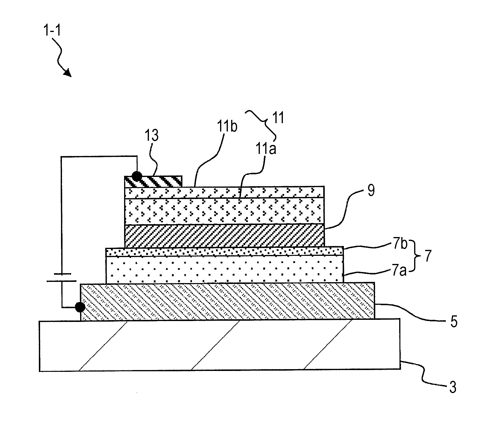
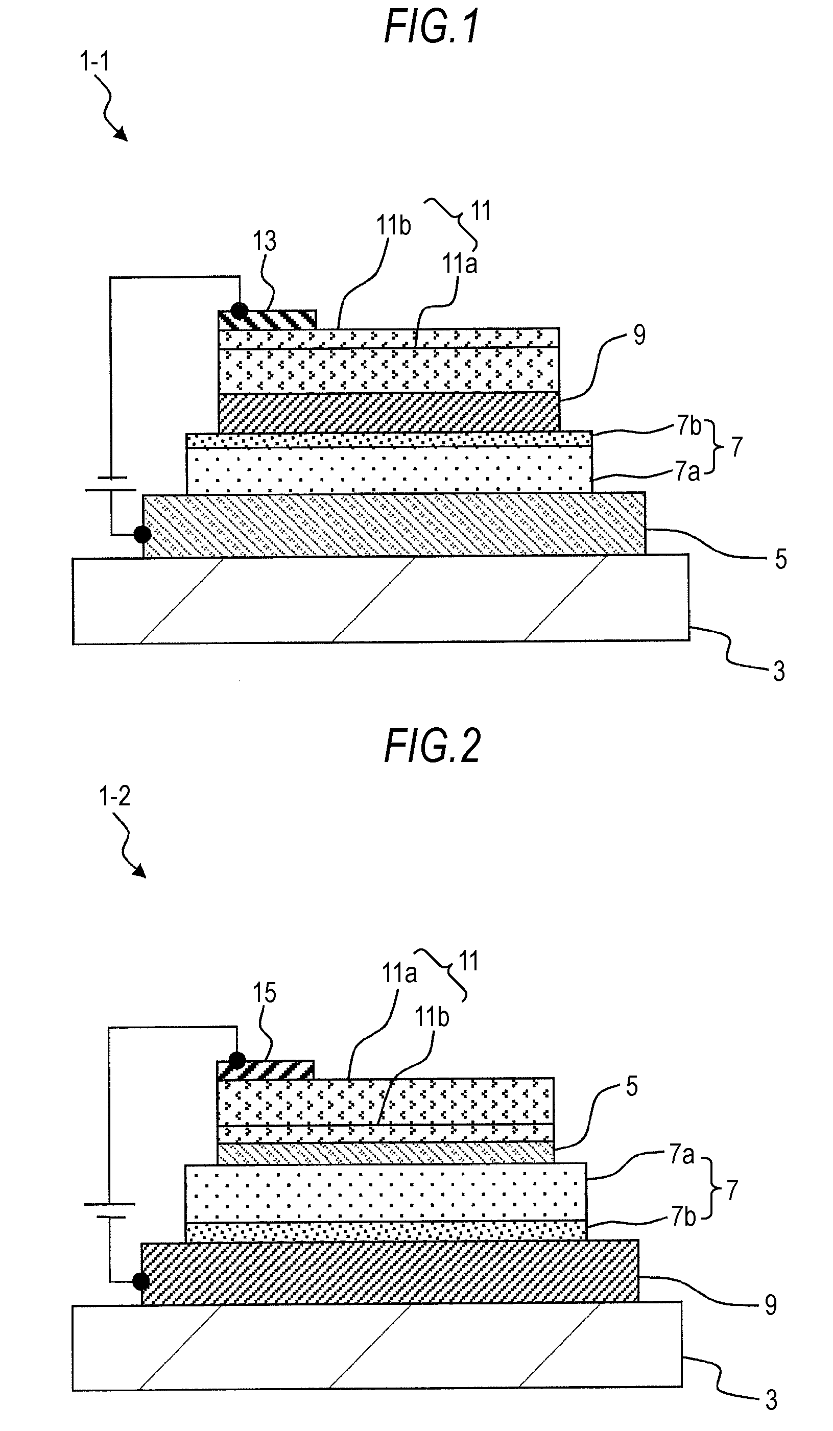
[0036]FIG. 1 is a cross sectional view schematically illustrating an organic electroluminescent device 1-1 of an embodiment of the present invention. The organic electroluminescent device 1-1 is a first example suited for top emission, and includes an anode 5 provided as a lower electrode on a substrate 3, an organic emission functional layer 7 overlaid on the anode 5, and a cathode 9 provided as an upper electrode on the organic emission functional layer 7. Further, an organic electrode film 11 and a cathode wire 13 are provided on the cathode 9. A characteristic of an embodiment of the present invention is that the organic electrode film 11 is formed using the materials described below.

[0037]The following description will be given through the case where the organic electroluminescent device 1-1 of the stacked configuration is a top-emitting device in which the light is drawn from the side of the cathode 9 opposite from the substrate 3. Details of each layer in this configuration w...

second embodiment

[0088]FIG. 2 is a cross sectional view schematically illustrating an organic electroluminescent device 1-2 according to another embodiment of the present invention. The organic electroluminescent device 1-2 is a second example suited for top emission, and differs from the First Embodiment in the order of stacking; namely, it has a reverse stacked configuration in which the cathode 9 and the anode 5 are used as the lower and upper electrodes, respectively. Note that each layer of the organic electroluminescent device 1-2 will be described with reference to the same reference numerals used in the First Embodiment, and no detailed descriptions will be given concerning the materials of these layers because the same materials are used as in the First Embodiment.

[0089]Specifically, the organic electroluminescent device 1-2 includes a cathode 9 provided as a lower electrode on a substrate 3, an organic emission functional layer 7 overlaid on the cathode 9, and an anode 5 provided as an upp...

third embodiment

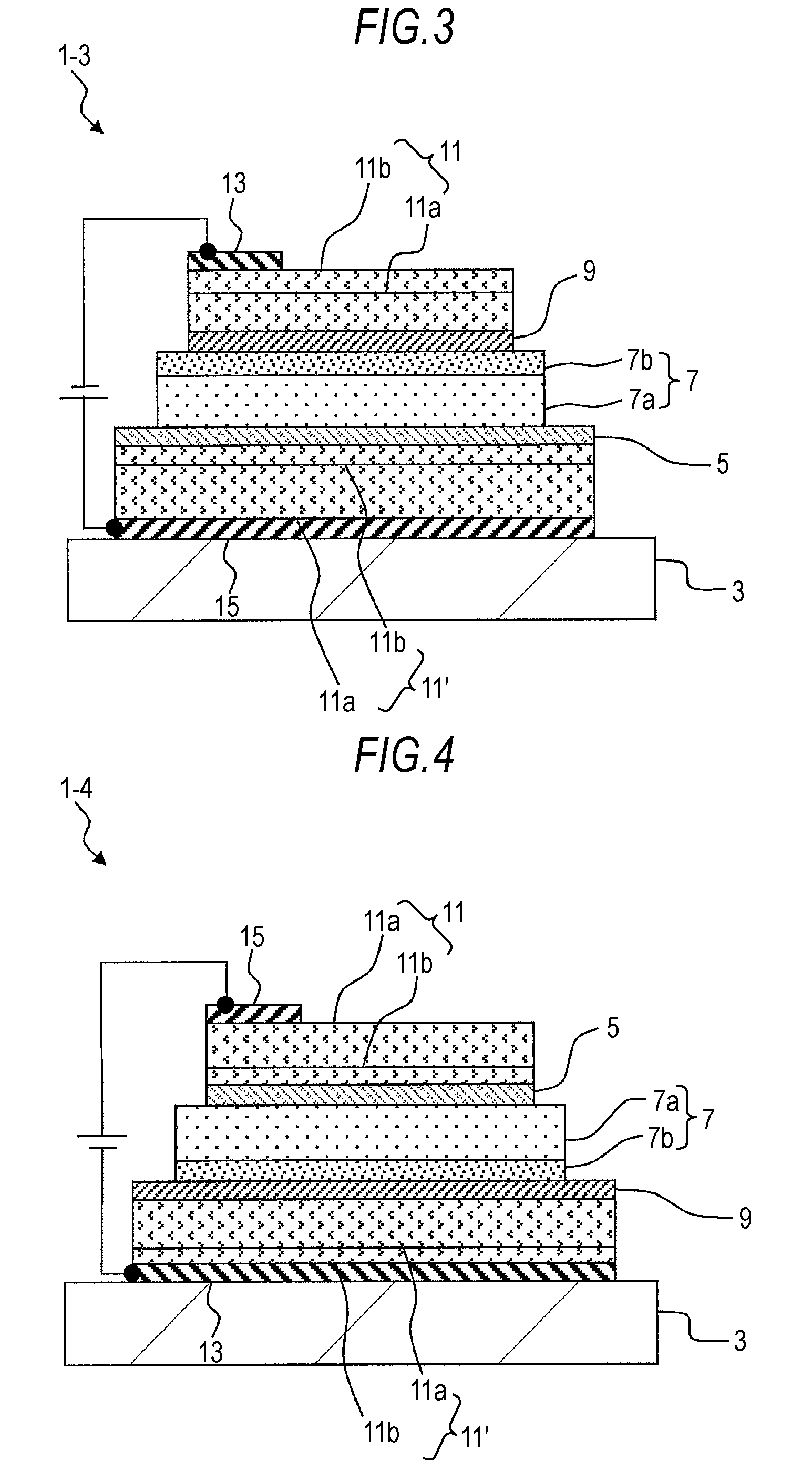
[0098]FIG. 3 is a cross sectional view schematically illustrating an organic electroluminescent device 1-3 according to another embodiment of the present invention. The organic electroluminescent device 1-3 is a first example suited for top-and-bottom emission, and additionally includes an organic electrode film 11′ on the lower electrode anode 5 side in the configuration of the First Embodiment. Note that each layer of the organic electroluminescent device 1-3 will be described with reference to the same reference numerals used in the First Embodiment, and no detailed descriptions will be given concerning the materials of these layers because the same materials are used as in the First Embodiment.

[0099]Specifically, the organic electroluminescent device 1-3 has a stacked configuration in which an anode wire 15 and the organic electrode film 11′ are formed on the substrate 3 in this order, and in which the anode 5, the organic emission functional layer 7, the cathode 9, the organic ...


PUM

PropertyMeasurementUnit
thicknessaaaaaaaaaa
deposition rateaaaaaaaaaa
thicknessaaaaaaaaaa

Abstract

An organic electroluminescent device, includes: an anode and a cathode of inorganic conducting material; an organic emission functional layer interposed between the anode and the cathode, and that includes an organic emissive layer; and an organic electrode film provided in contact with an outer side of at least one of the anode and the cathode, wherein the organic electrode film is formed using at least one of (I) a combination of a polycyclic aromatic hydrocarbon compound having a backbone of 3- to 7-membered rings, and a benzoimidazole derivative having a substituent in the benzene ring, and (II) an azatriphenylene derivative.

Description

BACKGROUND OF THE INVENTION[0001]1. Field of the Invention[0002]The present invention relates to organic electroluminescent devices (also known as organic EL devices) and display devices, particularly to organic electroluminescent devices and display devices that include a thin electrode of inorganic material protected by a conductive organic material.[0003]2. Description of the Related Art[0004]Organic electroluminescent devices (also known as organic EL devices) utilizing the electroluminescence (hereinafter, “EL”) of organic materials are structured to include a stacked organic emission functional layer of an organic hole transport layer and an organic emissive layer between the anode and cathode. Such organic electroluminescent devices are of interest as light-emitting devices capable of emitting bright light by low-voltage DC driving.[0005]In such organic electroluminescent devices, it has been proposed to stack a conductive organic film on the cathode or anode to complement co...

Claims


Application Information

Patent Timeline
Patent Type & Authority Patents(United States)
IPC IPC(8): H01L51/54
CPCH01L51/5206H01L51/5221H01L51/0072H01L51/0081H10K59/123H10K85/324H10K85/6572H10K59/80517H10K59/80523H10K50/816H10K50/826
Inventor IMAI, YOSHIAKIKIJIMA, YASUNORIKAMBE, EMIKOYOSHINAGA, TADAHIKO
Owner JOLED INC
Why Eureka
Try Eureka