
Systems structures and materials for electronic device cooling

Active Publication Date: 2013-11-19
LATENT HEAT SOLUTIONS LLC
View PDF52 Cites 141 Cited by
  • Summary
  • Abstract
  • Description
  • Claims
  • Application Information

AI Technical Summary

Benefits of technology

The patent describes a method to make a personal computing device by putting a material called temperature management material over parts that generate heat. These parts are then enclosed in a housing and cured. This material helps to manage the temperature and dissipate the heat. This helps to make the device work better and last longer.

Problems solved by technology

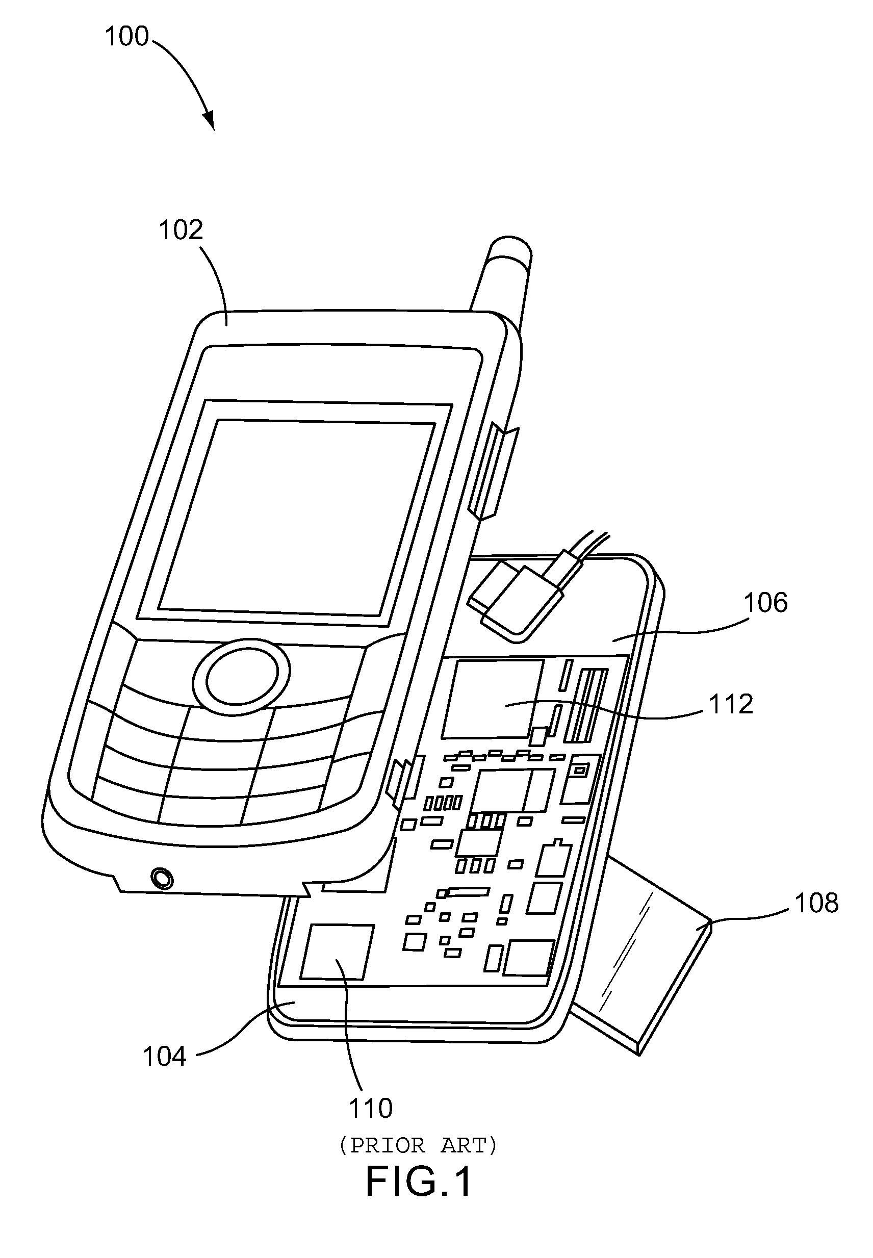
However, the higher processing power and demands of modern electronic devices only adds to the heat generated by these devices.
The temperatures generated by such devices have been reported widely in the news and have even led to user injuries and device damage.
This overheating also causes hotspots and hot areas on the surface of the device thereby causing discomfort or injury to the human user and therefore there is a need to manage this heat.
Reducing the speed and power of the components is not preferable since this creates inefficiencies, prolonged wait times for results, reduced download speeds, etc.
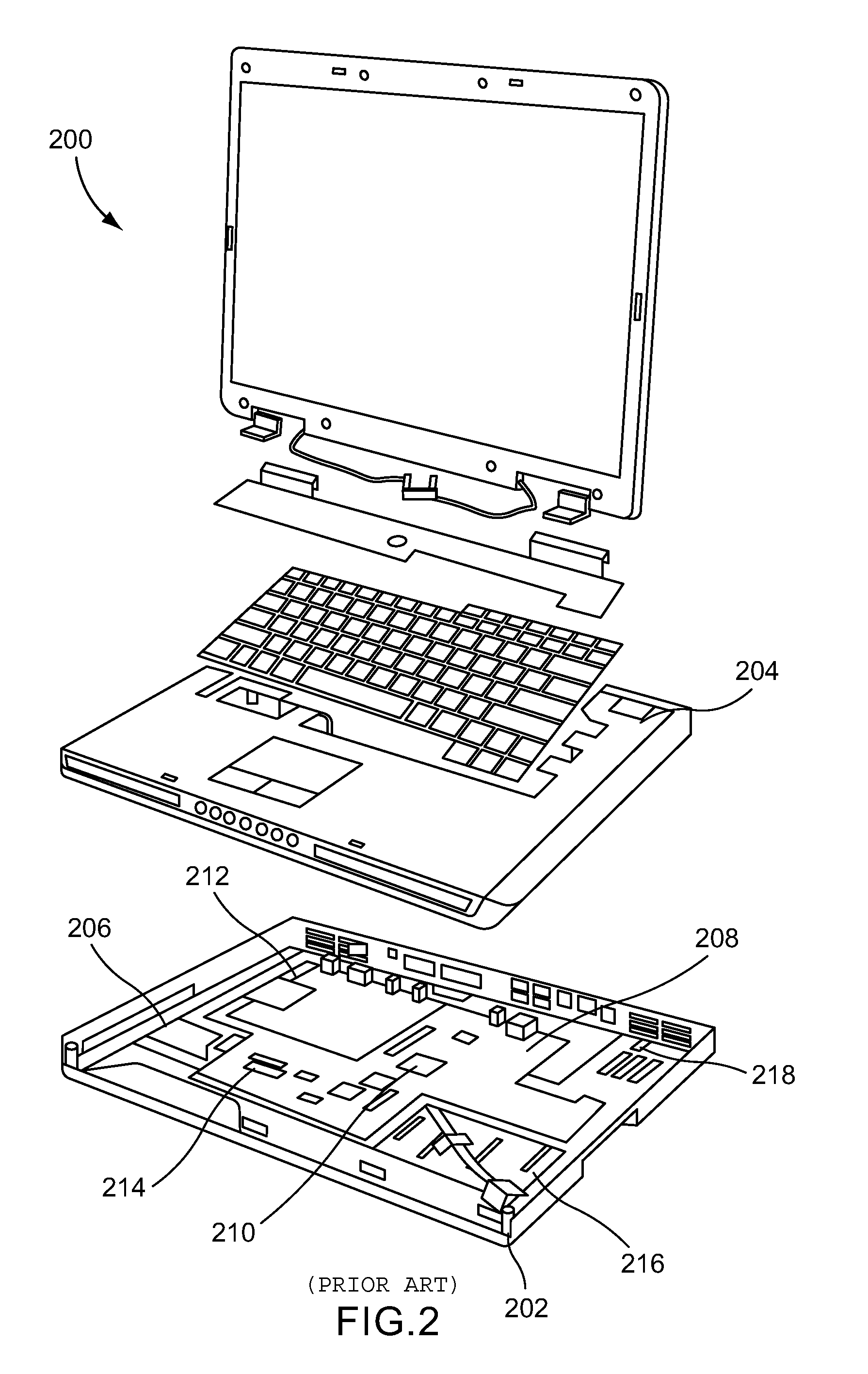
This is made more difficult by the shrinking of the component and total device area, all leading to a larger heat flux per unit area.
PCMs have been used widely in the textile and fabrics industries but have not been effectively utilized or disclosed in the electronics fields, particularly when utilized to effect heat storage and removal.
The use of PCMs in the electronics industries has thus far been limited to mixing micro-encapsulated PCMs into an epoxy or otherwise mixing waxes and gels.
No one has been able to figure out how to effectively take these materials, form them, lock them into place in a complicated and sensitive electronic assembly, maintain high latent heats with thermal conductivity while conforming to the confines of an enclosed electronic device or other processor confined within a sealed or other casing.

Method used


Image

  • Systems structures and materials for electronic device cooling
  • Systems structures and materials for electronic device cooling
  • Systems structures and materials for electronic device cooling

Examples


Embodiment Construction

[0037]Throughout this specification references are made to the use of various materials, combinations, chemical formulations and other aspects that may be used in various combinations to form one or more materials, end products, or compositions in accordance with aspects of the present invention. It should be understood, both to one of skill in the art as well as the examining divisions in the United States Patent Office and Patent Offices throughout the world, that each of the lists of materials, examples, and other embodiments are included herein in order to teach one of skill in the art that they may be combined into various alternative embodiments, without requiring specific claim permutations of these individual features. The claims as presented herein, as well as any potential future amendments to those claims, may include one or more combinations of these materials, ranges and other alternatives without departing from the spirit and scope of the invention described herein. In...


PUM

PropertyMeasurementUnit
Temperatureaaaaaaaaaa
Fractionaaaaaaaaaa

Abstract

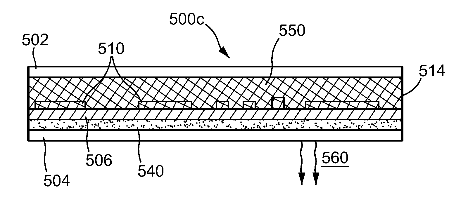
An electronic device having one or more components that generate heat during operation includes a structure for temperature management and heat dissipation. The structure for temperature management and heat dissipation comprises a heat transfer substrate having a surface that is in thermal communication with the ambient environment and a temperature management material in physical contact with at least a portion of the one or more components of the electronic device and at least a portion of the heat transfer substrate. The temperature management material comprises a polymeric phase change material having a latent heat of at least 5 Joules per gram and a transition temperature between 0° C. and 100° C., and a thermal conductive filler.

Description

FIELD OF THE INVENTION[0001]In general, the present invention relates to systems, structures and compositions used to enhance the performance of electronic devices and components by increasing the cooling efficiency and capacity of the devices and components.BACKGROUND OF THE INVENTION[0002]Electronic devices, and in particular personal electronic devices such as smart phones, tablets, and laptop computers, have gone through major evolutions in the past decade. The devices themselves have become smaller and smaller, while at the same time, utilizing more and more processing power, advanced communications electronics, and fewer moving parts. For example, and most particular to aspects of the present invention, the small size of modern personal electronics has demanded that mechanical cooling systems, such as fans and other air handling devices, be removed and replaced with passive cooling systems. However, the higher processing power and demands of modern electronic devices only adds...

Claims


Application Information

Patent Timeline
IPC IPC(8): H05K7/20
CPCH05K7/20454H05K3/30H05K7/2039G06F1/203H01L23/427H01L23/373H01L23/3737H01L23/42H01L2924/0002H05K1/0204H05K3/284H05K3/285Y10T29/49146H05K1/0209H01L2924/00H05K3/28
Inventor HARTMANN, MARKRODA, GREG
Owner LATENT HEAT SOLUTIONS LLC
Learn More