
System and method for programmable automatic testing of power supplied

a technology of automatic power supply and system architecture, applied in power supply testing, testing circuits, instruments, etc., can solve the problem of relatively high cost and achieve the effect of reducing cost and cos

Inactive Publication Date: 2013-11-19
SYNERGISTIC TECH SOLUTIONS
View PDF6 Cites 18 Cited by
  • Summary
  • Abstract
  • Description
  • Claims
  • Application Information

AI Technical Summary

Benefits of technology

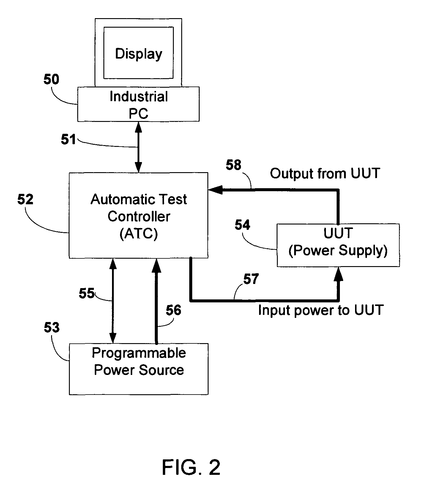
[0009]One key part of the current invention is the Automatic Test Controller (ATC). It serves as the core of the automatic test system. FIG. 2 shows the signal flow of the current invention. The ATC has two serial communication links. One serial link 51 connects the ATC with the industrial PC. The other serial link 55 connects the ATC with the programmable power source. The output of the programmable power source sends the power to the ATC via the power cable 56. The input of the power supply UUT receives power from the ATC via power cable 57; and the output of the power supply UUT is connected to the ATC via power cable 58. A Digital Signal Processor (DSP) chip inside the ATC works as the main control device for the ATC. The various components of the automatic test system, such as power analyzing module, electronic load module and precision multi-channel DC measurement module, etc., are dedicated modules mounted inside the ATC. These modules are linked to the DSP with board level interface, such as General Purpose Input-output (GPIO) pins, Analog-to-Digital Converter (ADC) inputs, Pulse Width Modulated (PWM) outputs and Serial Peripheral Interface (SPI) ports. The dedicated automatic test components described above are much lower cost compared to the standard test devices used in the conventional automatic test systems. The board level interface between various components and the DSP is much lower cost than the external interface, e.g. IEEE488 bus, used in the conventional automatic power supply test systems.
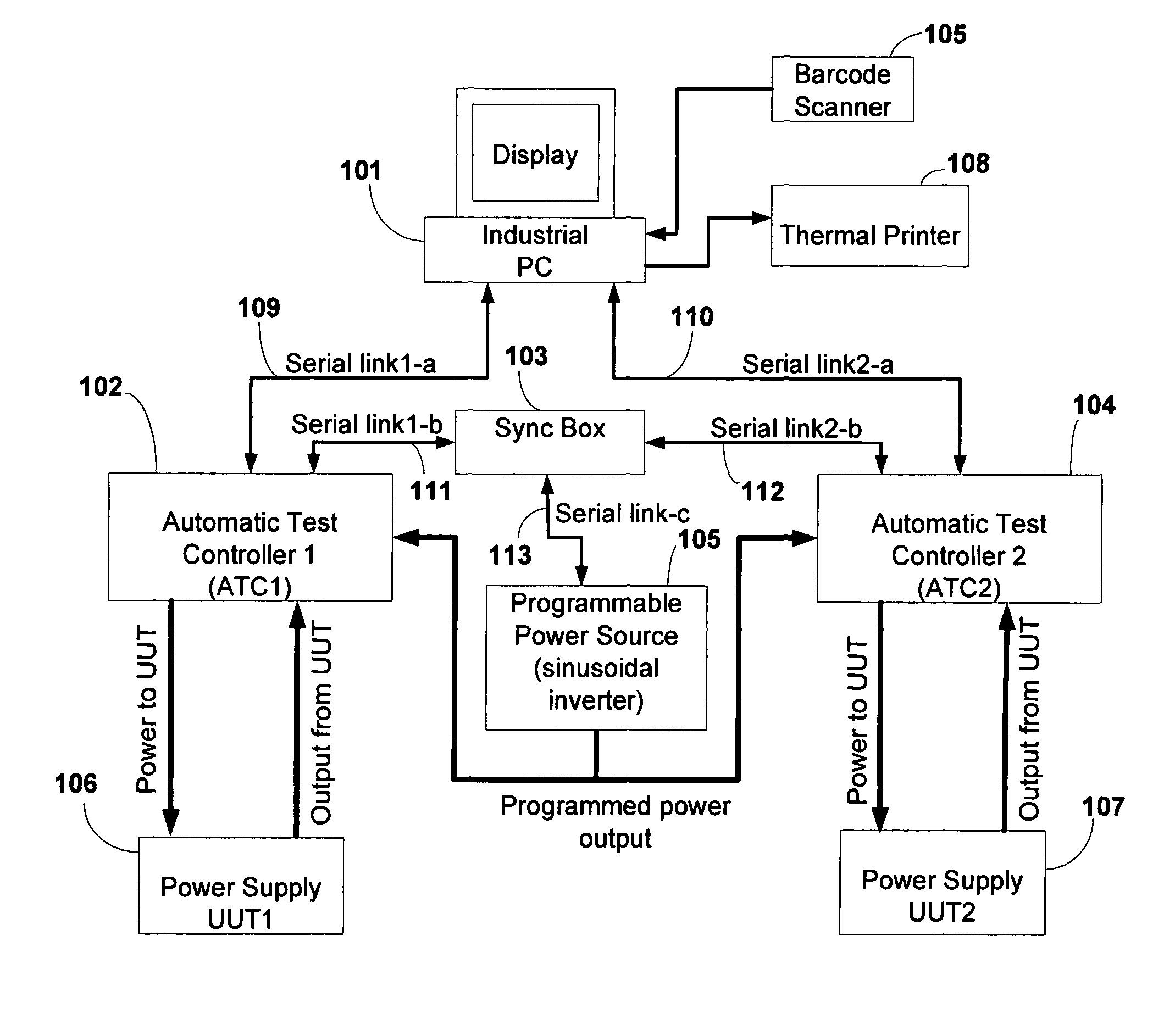
[0014]Another aspect of the current invention is to allow a single operator to operate two or more test units simultaneously with a single PC and programmable power source. This is achieved by using a “Sync Box” that synchronizes two or more test units (ATCs) so they can share the same programmable power source. Operating two ATC simultaneously further reduces the equipment cost and improves the production line efficiency.

Problems solved by technology

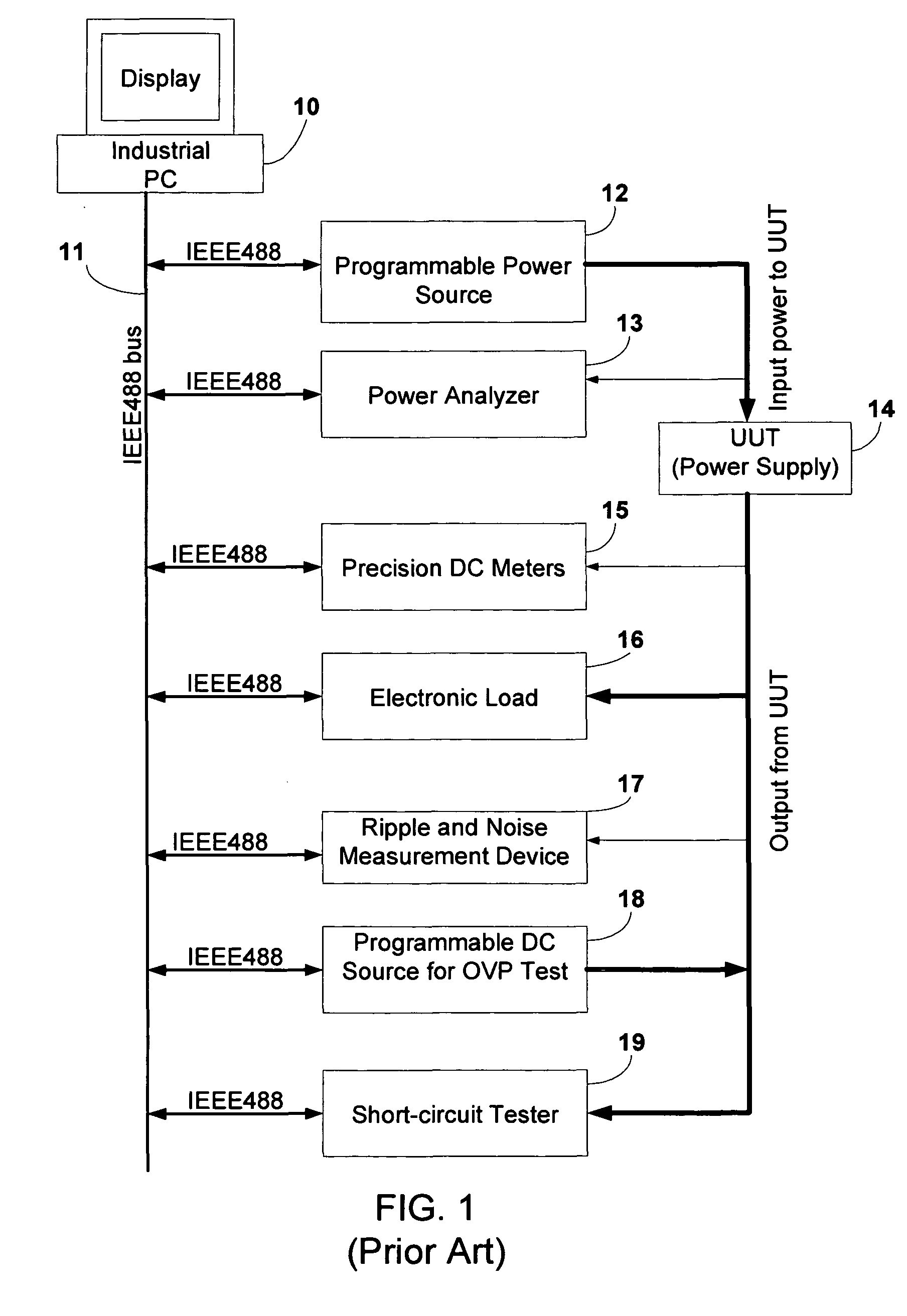
While this conventional architecture has the flexibility to allow the user to program each system components freely, its drawback is the relatively high cost.

Method used


Image

  • System and method for programmable automatic testing of power supplied
  • System and method for programmable automatic testing of power supplied
  • System and method for programmable automatic testing of power supplied

Examples


Embodiment Construction

[0020]FIG. 3 illustrates the block diagram of the preferred embodiment of the current invention. The industrial PC 101 is connected to two ATC's via serial links 109 and 110. The programmable power source 105 supplies power to both ATC's (102&104). The pace of the two ATC's is synchronized by the Sync Box 103. The Sync Box receives requests to set up the programmable power source from both ATC's via serial links 111 and 112. The requests generally come at slightly different time instances. The Sync Box waits for both requests to arrive before setting up the programmable power source via serial link 113. This ensures both ATC's to have stable power source at specified voltage and frequency for the upcoming test set. The configuration of a typical test set generally consists of the following parts: 1) Set the power source voltage and frequency; 2) set the load type (Constant Current—CC, Constant Voltage—CV or Constant Resistance—CR load) and load value (A, V or Ohm); 3) select paramet...


PUM


Abstract

A cost-effective system architecture and apparatus for programmable automatic power supply testing. The system utilizes board level interface between various system testing modules and an Automatic Test Controller (ATC). The ATC receives coded test requests from the software on an industrial PC and control the various testing modules inside ATC to execute the tests. Test results were sent back to the PC and saved in a result file. A single industrial PC can control two or more ATC's and test two or more power supply units simultaneously. The ATC based test system is lower cost than the conventional Automatic Test Equipment which uses device level interface and standardized test devices.

Description

CROSS-REFERENCE TO RELATED APPLICATIONS[0001]Not applicable.FIELD OF THE INVENTION[0002]This invention relates to a cost-effective system architecture and apparatus for programmable automatic power supply testing.STATEMENT REGARDING FEDERALLY SPONSORED RESEARCH OR DEVELOPMENT[0003]Not applicable.REFERENCE TO SEQUENCE LISTING, A TABLE, OR A COMPUTER PROGRAMLISTING COMPACT DISC APPENDIX[0004]Not applicable.BACKGROUND OF THE INVENTION[0005]An automatic power supply test system is used to test the performance of a power supply. These test systems automatically measure the parameters such as input voltage, current, power, power factor, output voltage, current, ripple and noise, short-circuit protection, over-voltage protection (OVP) and over-current protection (OCP) of a power supply. An automatic power supply test system is often used in power supply production line to ensure products meet the specifications before they are packed for shipment. An automatic power supply test system usua...

Claims


Application Information

Patent Timeline
Patent Type & Authority Patents(United States)
IPC IPC(8): G01R31/40G01R31/42
CPCG01R31/2834
Inventor LIU, GUANGCHOI, ALEX KURNIA
Owner SYNERGISTIC TECH SOLUTIONS
Learn More