
Balanced multiple groupings of beta stirling machines

a technology of stirling machine and beta free piston, which is applied in the direction of machines/engines, safety/regulation devices, hot gas positive displacement engine plants, etc., can solve the problems of axial oscillation vibration, vibrational torque, and problem is made more complicated, so as to prevent or minimize vibration, reduce construction costs, and prevent or minimize vibration.

Inactive Publication Date: 2013-11-26
SUNPOWER
View PDF4 Cites 0 Cited by
  • Summary
  • Abstract
  • Description
  • Claims
  • Application Information

AI Technical Summary

Benefits of technology

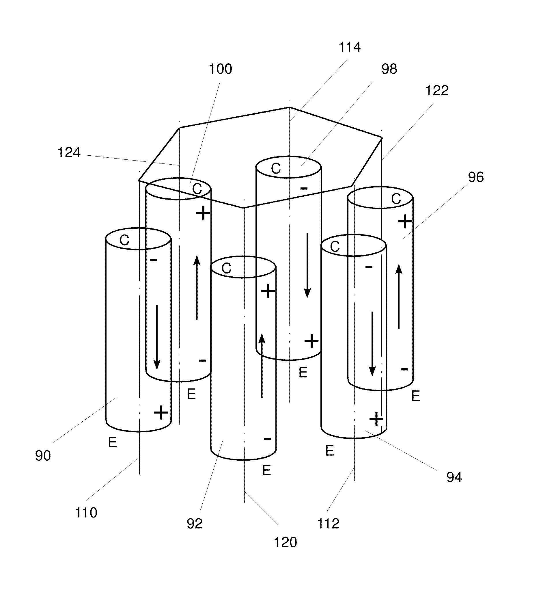
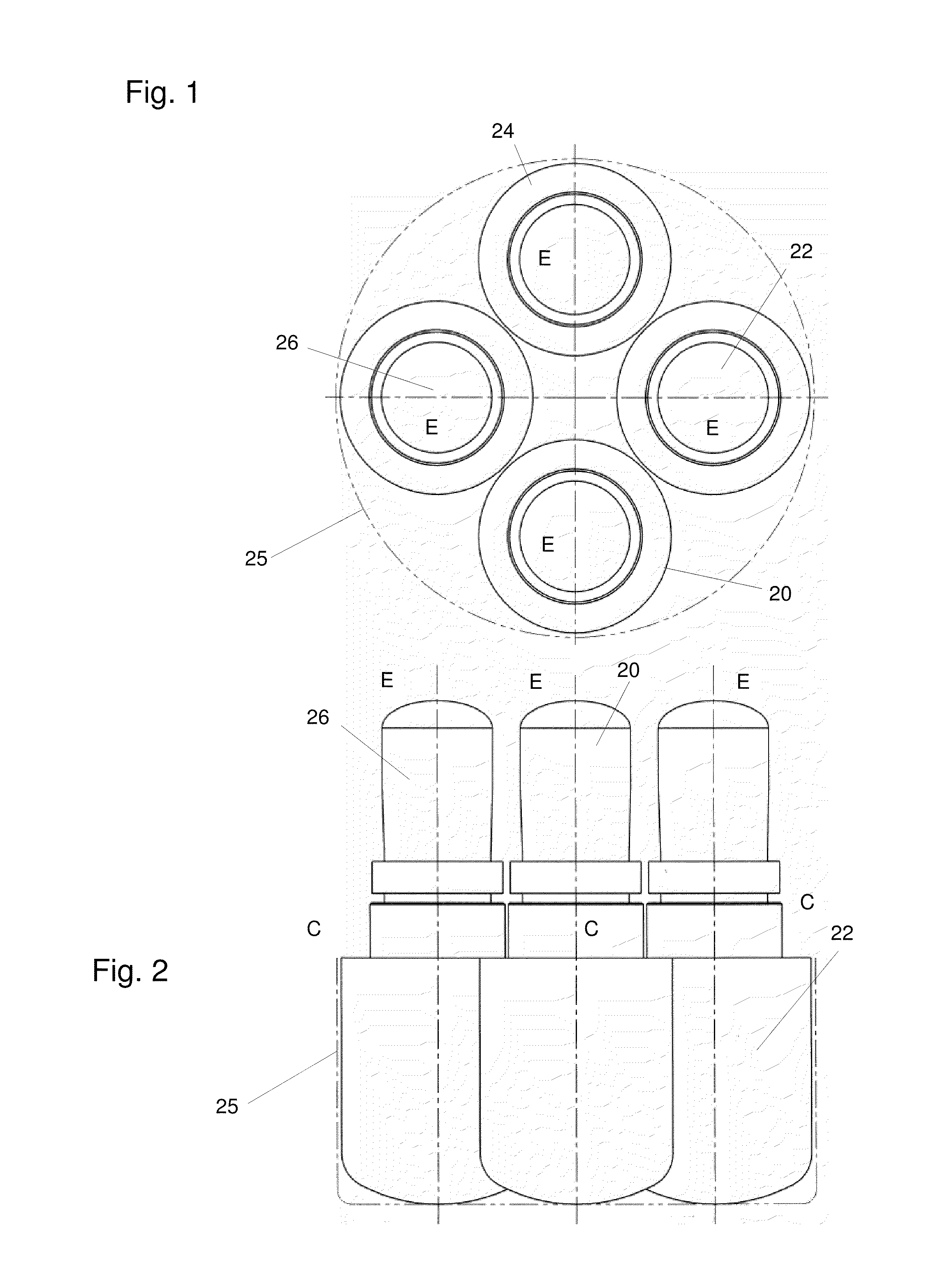
The present invention is a group of multiple free-piston Stirling (FPS) machines arranged and connected for preventing or minimizing vibration. The FPS machines have outer housings and internal reciprocating composite masses, including the masses of a prime mover or load connected to the FPS machines. The FPS machines are rigidly connected together and each machine is configured and oriented on its axis for operating in phase with the diagonally opposite FPS machine. The FPS machines can be placed in nearby adjacent or laterally spaced positions, and the arrangement allows for economies of scale and mass production. The invention provides a more efficient and cost-effective solution for some applications compared to single or a few larger machines.

Problems solved by technology

These axially alternating forces cause axially oscillating vibration.
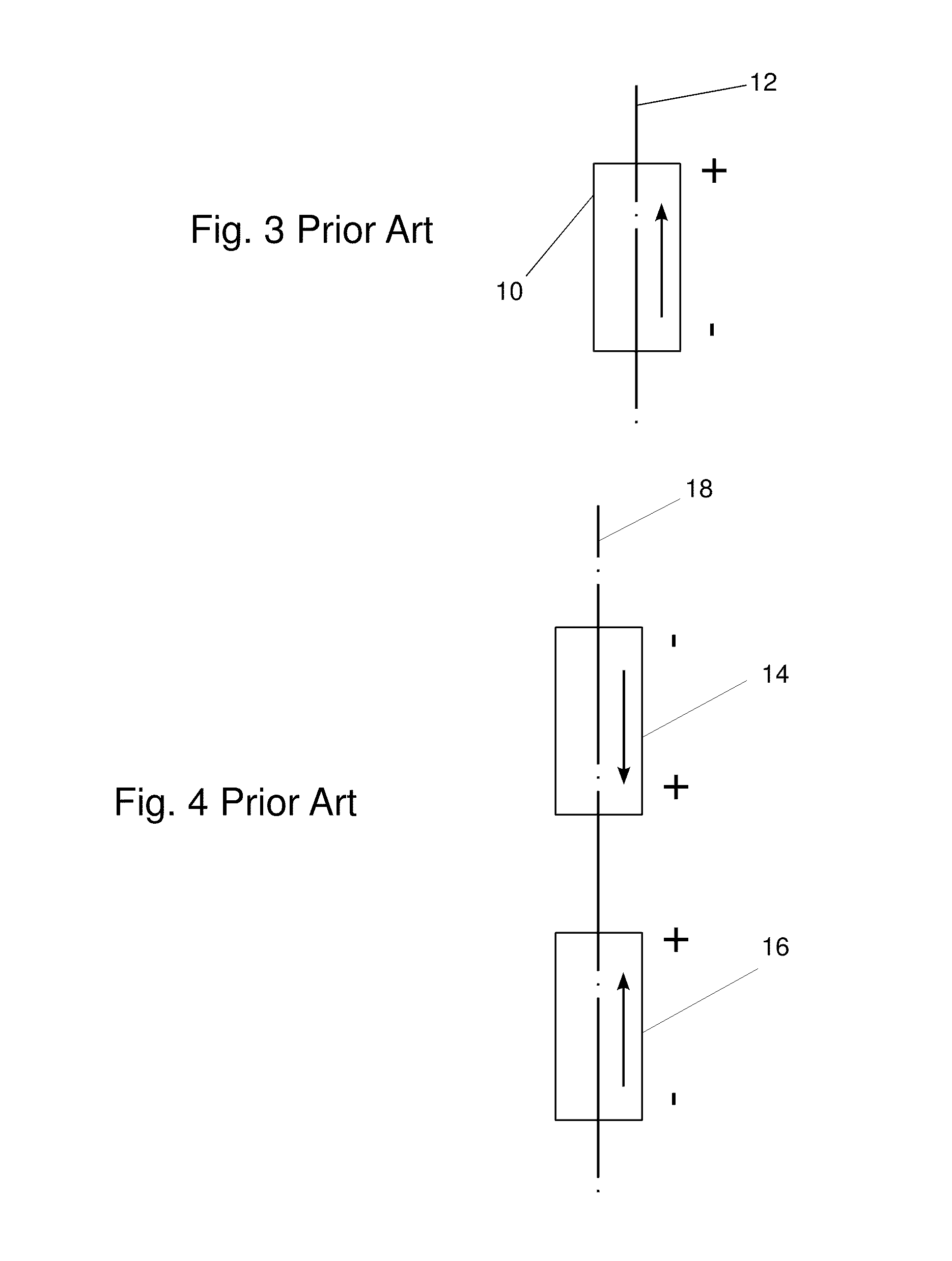
However, if two beta FPS machines are not positioned coaxially, they either form a couple or they have a net translational vibration force.
A couple applies a torque to the entire composite mass of the machines which results in a vibrational torque.
When the axes are neither parallel nor coaxial, the problem is made more complicated by the effect of the oblique resultants of the net vibrational forces and couples.

Method used


Image

  • Balanced multiple groupings of beta stirling machines
  • Balanced multiple groupings of beta stirling machines
  • Balanced multiple groupings of beta stirling machines

Examples


Embodiment Construction

[0043]Provisional patent application Ser. No. 61 / 106,647 and Ser. No. 61 / 116,477 are hereby incorporated by reference into this application.

[0044]Definition of Terms

[0045]In describing the invention and its embodiments, there are terms used that are desirably defined and therefore the following definitions are stated.

[0046]FPS—an abbreviation for free piston Stirling.

[0047]Beta FPS machine—one beta Free piston Stirling engine or one beta free piston Stirling cooler. A beta FPS machine has a housing, a reciprocating power piston and a reciprocating displacer. They are well known in the prior art and groupings of them are the subject of this invention.

[0048]Balanced group of FPS machines—multiple, rigidly connected beta FPS machines for which the sum of their translational force vectors and the sum of their couples (torque vectors), both resulting from the acceleration (F=ma) forces of their reciprocating pistons, displacers and masses attached to them, both sum to zero.

[0049]Thermody...


PUM


Abstract

Multiple free-piston Stirling (FPS) machines are arranged in a group and connected for preventing or minimizing vibration. A first set of identical beta FPS machines are arranged in a mechanically co-directional orientation and configured to reciprocate in thermodynamically synchronous reciprocation with each other. The first set has axes of reciprocation intersecting a first point. A second set of beta FPS machines are arranged in a mechanically co-directional orientation that is the same as the mechanical orientation of the first set of beta FPS machines and are configured to reciprocate in thermodynamically synchronous reciprocation with each other but in thermodynamically opposed reciprocation to the first set. The FPS machines of the second set are identical to the FPS machines of the first set and have axes of reciprocation intersecting a point, which may be a point at infinity.

Description

CROSS-REFERENCES TO RELATED APPLICATIONS[0001]This application claims the benefit of U.S. Provisional Application No. 61 / 106,647 filed 20 Oct. 2008 U.S. Provisional Application No. 61 / 116,477 filed 20 Nov. 2008. The above prior applications are hereby incorporated by reference.STATEMENT REGARDING FEDERALLY-SPONSORED RESEARCH AND DEVELOPMENT[0002](Not Applicable)REFERENCE TO AN APPENDIX[0003](Not Applicable)BACKGROUND OF THE INVENTION[0004]1. Field of the Invention[0005]This invention relates generally to Stirling cycle machines and more particularly to groups of beta free piston Stirling cycle engines and beta free piston Stirling cycle coolers that are balanced to prevent or minimize vibration.[0006]2. Description of the Related Art[0007]Stirling machines have been known for nearly two centuries but in recent decades have been the subject of considerable development because they offer important advantages. Modern versions have been used as engines and heat pumps for many years in a...

Claims


Application Information

Patent Timeline
Patent Type & Authority Patents(United States)
IPC IPC(8): F01B29/10
CPCF02G1/0435F02G1/044F02G2270/60F02G2275/10F02G1/045
Inventor BEALE, WILLIAM T.WOOD, JAMES GARY
Owner SUNPOWER
Learn More