Check patentability & draft patents in minutes with Patsnap Eureka AI!

Microreactor system

a microreactor and microreactor technology, applied in the direction of liquid gas reaction of thin film type, gas-gas reaction process, instruments, etc., can solve the problem that the characteristics of synthesis reaction with using the microreactor cannot be fully obtained, and achieve the effect of high mixing performan

Inactive Publication Date: 2013-11-26
HITACHI LTD
View PDF18 Cites 4 Cited by
  • Summary
  • Abstract
  • Description
  • Claims
  • Application Information

AI Technical Summary

Benefits of technology

The present invention provides a microreactor system with high mixing performance even at small flow rates without the need for a manifold. This system is suitable for multi-step reactions and can improve reaction efficiency without increasing the size of the reactor.

Problems solved by technology

However, when trying to apply the microreactor into the multi-step reaction, there may be brought about cases where the characteristics in the synthesis reaction with using the microreactor cannot be fully obtained, only if connecting the microreactors for use of the one (1)-step reaction in series.
However, as was mentioned above, when applying the microreactor into the multi-step reaction, there are following problems:

Method used


Image

  • Microreactor system
  • Microreactor system
  • Microreactor system

Examples


embodiment 1

[0063]Following to the above, explanation will be given on the structure of the microreactor 109 according to the present invention, in particular, the structure thereof according to a first embodiment (an embodiment 1), in more details thereof, by referring to FIGS. 5 to 11 attached herewith.

[0064]First of all, FIG. 5 shows an exploded perspective view of the microreactor, according to the embodiment 1 of the present invention, and FIG. 6 shows a channel forming plate for building up the structure of that microreactor.

[0065]As is shown in FIG. 5, the microreactor according to the embodiment 1 of the present invention is made up with an upper-side plate 504, a lower-side plate 505 and a holder plate 506, i.e., three (3) pieces of plates in total. For those three (3) pieces of plates, packing not shown in the figure is inserted into a packing groove 509, each being formed on a surface thereof, respectively, and they are fixed by screws not shown in the figure, through a screw clamp, ...

embodiment 2

[0106]Next, explanation will be given on the structure of the microreactor, according to a second embodiment (an embodiment 2) of the present invention, by referring to FIGS. 12A and 12B and 13A and 13B.

[0107]First of all, FIG. 12A is a plane view for showing the channel configuration in the microreactor according to the second embodiment (the embodiment 2) of the present invention, and FIG. 12B is a perspective view thereof.

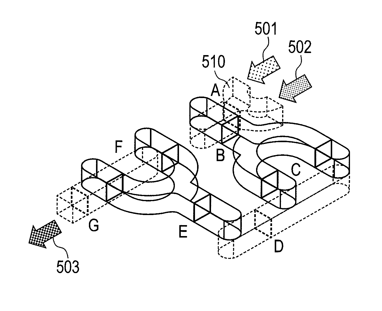
[0108]The channel 510 within the microreactor according to the present embodiment 2 is made up with an upper-side portion and a lower-side portion, wherein the solution 501 of reactant A and the solution 502 of reactant B, which are introduced, move into the normal-line direction from the lower-side channel up to the upper-side channel and also change the route into the left direction perpendicular to the channel direction of the upstream side, at the channel changing portion 704. And at the channel dividing portion 701, the channel is divided into the left and ...

embodiment 3

[0116]Further, explanation will be given on the channel configuration of a microreactor, according to a third embodiment (an embodiment 3) of the present invention, by referring to FIG. 14. This FIG. 14 is a plane view for showing the microreactor, according to the third embodiment (the embodiment 3) of the present invention, in particular, the channel configuration thereof.

[0117]As is shown in this figure, the channel 501 is made up with an upper-side portion and a lower-side portion, wherein a fluid including the solution 501 of reactant A and the solution 502 of reactant B moves into the normal-line direction from the lower-side channel up to the upper-side channel, and also change the route into the left direction perpendicular to the channel direction of the upstream side. Thereafter, the fluid is split into the left and the right directions at the channel dividing portion 701, and each moves into the normal-line direction from the upper-side channel down to the lower-side chan...


PUM


Abstract

In relation to a microreactor, and also a microreactor system applying the same therein, not producing any dead volume therein, and thereby achieving a high level of mixing properties even at a low solution flow rate and having a simple structure thereof, disclosed herein are a microreactor and microreactor system, comprising a channel for mixing up at least two (2) types of fluids, and thereby conducting mixing / reacting of fluids by conducting the mixing / reacting of the fluids at least one (1) time, i.e., being suitable for so-called a multi-step reaction.

Description

TECHNICAL FIELD[0001]The present invention relates to a microreactor and also a microreactor system applying the same therein, and in particular, it relates to a microreactor and a microreactor system, having a channel for mixing at least two (2) kinds of fluids and thereby conducting mixing / reacting of the fluids by splitting / mixing the fluids at least one (1) time, i.e., being suitable for so-called multi-step reaction.BACKGROUND TECHNOLOGY[0002]In recent years, approaches are made, enthusiastically or actively, on an application of an apparatus, manufactured by a microprocessing technology, for mixing fluids within a micro channel, i.e., so-called a microreactor, also in a bio / medical field or a field of chemical reaction.[0003]Conventionally, many of the microreactors are designed, mainly targeting so-called “one-step reaction”, for mixing only 2 kinds of reactants and thereby progressing the reaction. However, in recent years, it is expected to apply the microreactor into so-ca...

Claims


Application Information

Patent Timeline
Patent Type & Authority Patents(United States)
IPC IPC(8): B01J8/00B01J19/00G05B1/00B01F5/06
CPCB01F5/0641B01F13/0059B01J19/0093B01J2219/00783B01J2219/00867B01J2219/00889B01J2219/00891B01F25/4321B01F33/30B01J19/00B01F25/00B01F35/00
Inventor ASANO, YUKAKOMIYAMOTO, TETSUROTOGASHI, SHIGENORIENDO, YOSHISHIGETSUDOME, HIDEKAZUKATO, HAJIME
Owner HITACHI LTD
Features
  • R&D
  • Intellectual Property
  • Life Sciences
  • Materials
  • Tech Scout
  • Unparalleled Data Quality
  • Higher Quality Content
  • 60% Fewer Hallucinations
Learn More