Triple-band antenna with low profile

a low-profile, triple-band antenna technology, applied in the direction of antenna details, slot antennas, antennas, etc., can solve the problems of not adapting to the present electronic device, complex structure of triple-band antennas, and large volume, and achieve the effect of compact structur

Inactive Publication Date: 2013-11-26
HON HAI PRECISION IND CO LTD
View PDF10 Cites 4 Cited by
  • Summary
  • Abstract
  • Description
  • Claims
  • Application Information

AI Technical Summary

Benefits of technology

[0006]A primary object, therefore, of the present invention is to provide a multi-band antenna with compact structure.

Problems solved by technology

However, the triple-band antenna is of complex structure, big volume and not adapt for present electronic device.

Method used


Image

  • Triple-band antenna with low profile
  • Triple-band antenna with low profile
  • Triple-band antenna with low profile

Examples


Embodiment Construction

[0012]Reference will now be made in detail to a preferred embodiment made in accordance with the present invention.

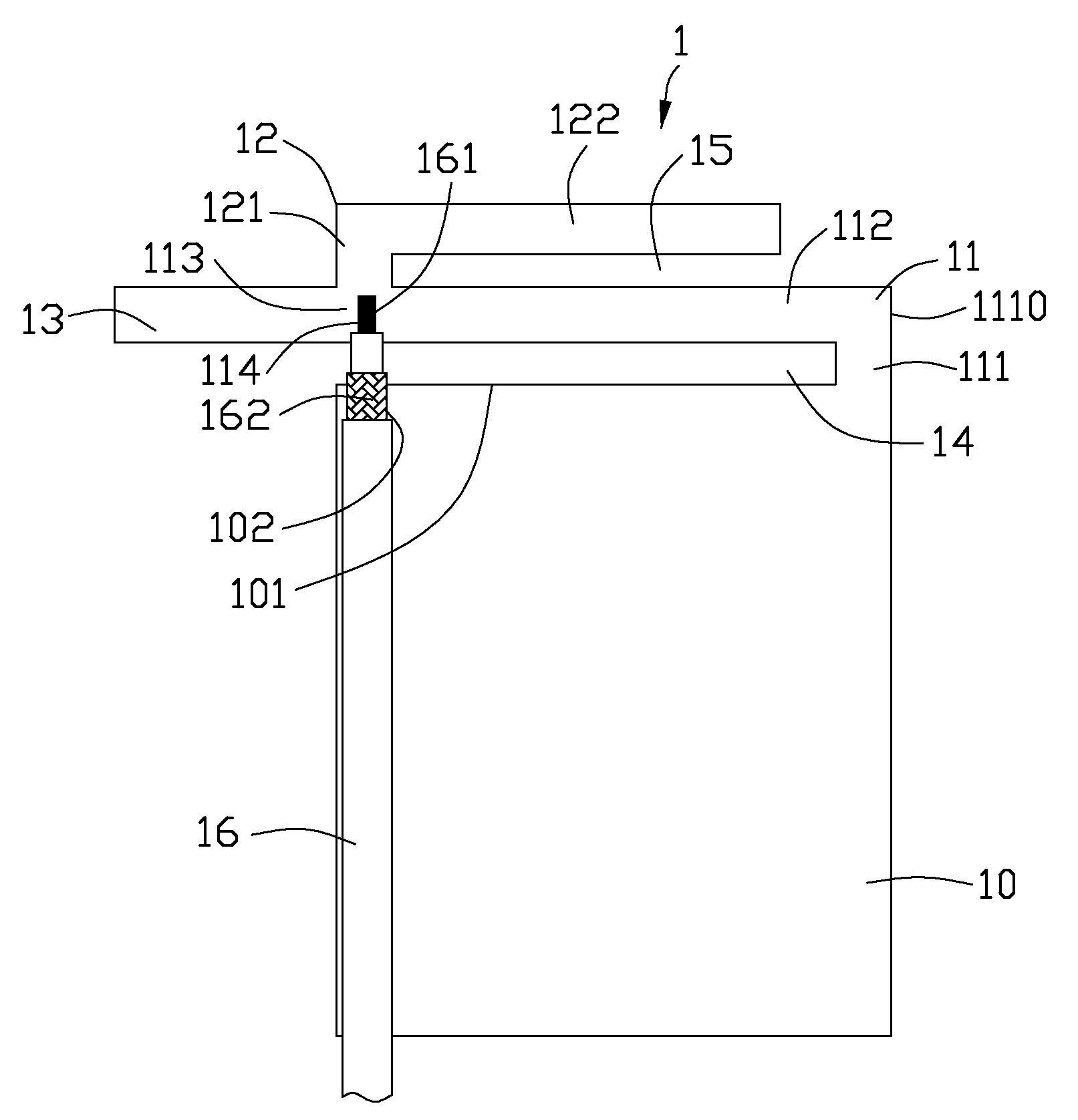
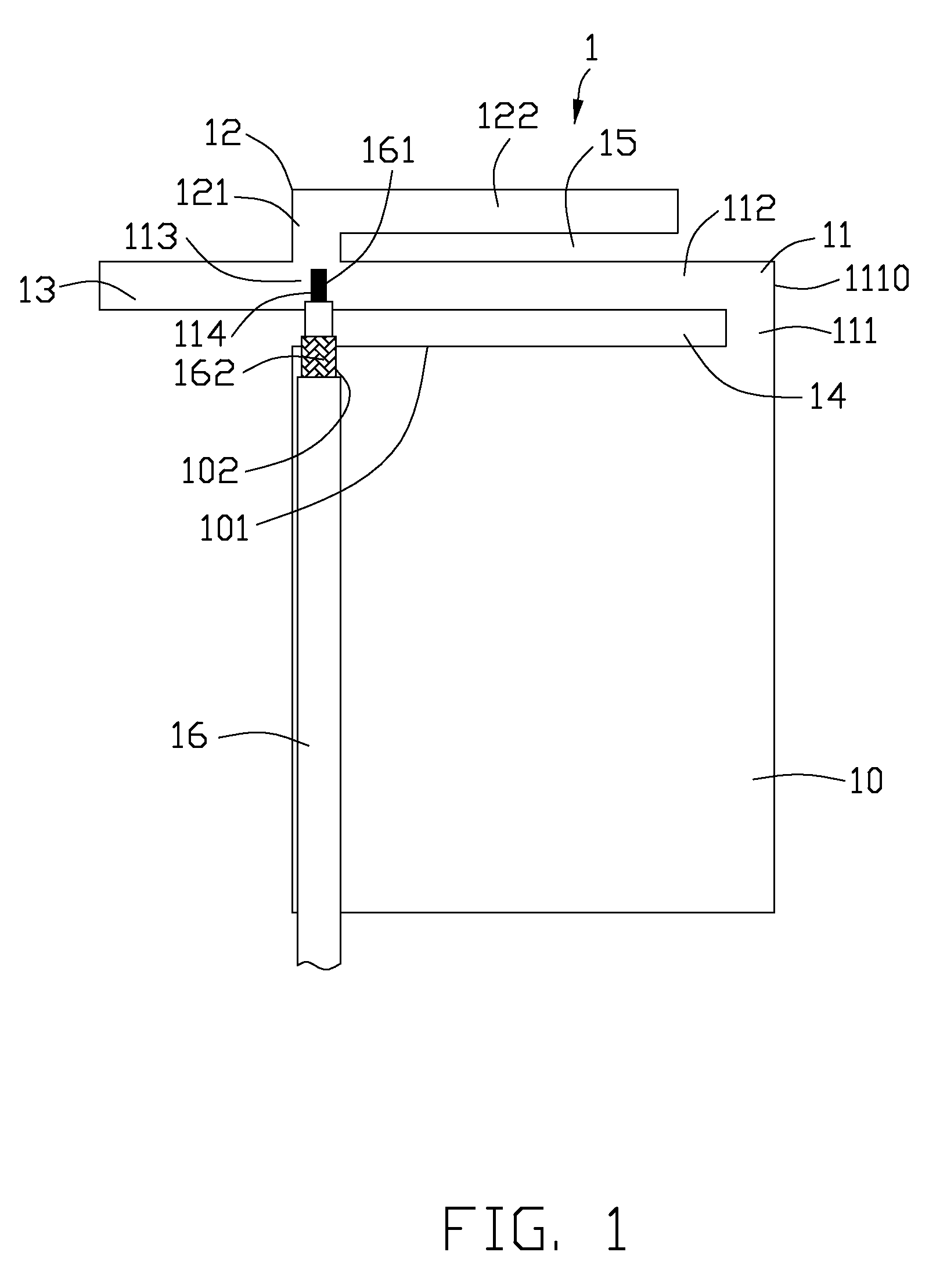
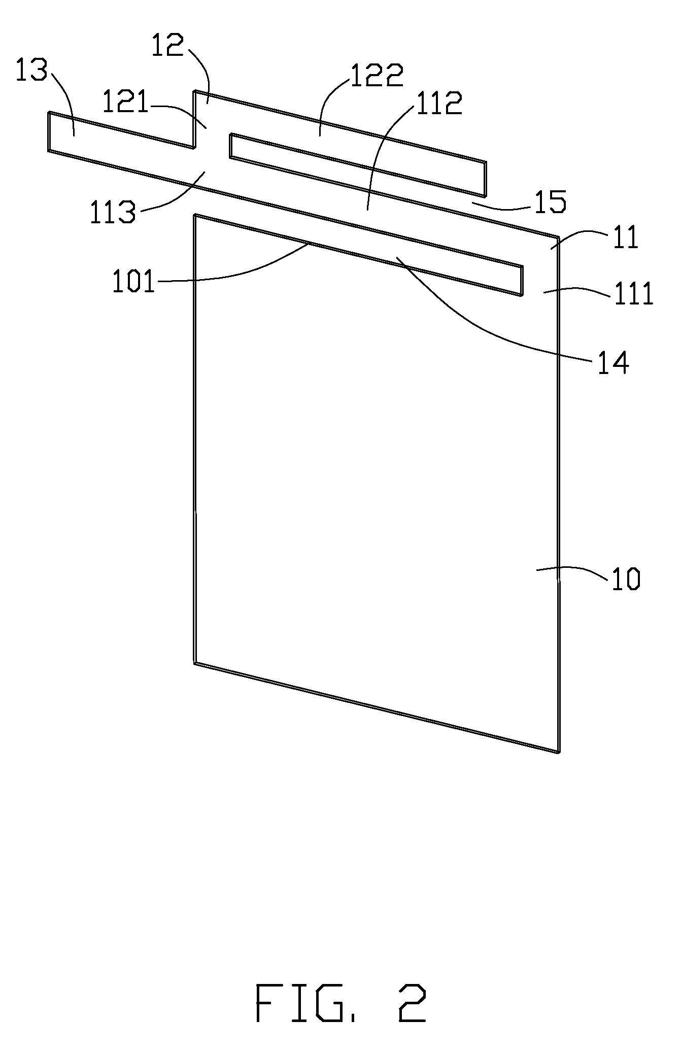
[0013]Reference to FIGS. 1 and 2, a multi-band antenna 1 made in accordance with a preferred embodiment of the present invention is shown. The multi-band antenna 1 comprises a grounding element 10, a first radiating arm 11, a second radiating arm 12, a third radiating arm 13 and a feeding line 16.

[0014]The grounding element 10 is of big rectangular metal patch, and has a first edge 101 and a grounding point 102. The first radiating arm 11 is of L shape and upward extends from the first edge 101 of the grounding element 10. The radiating arm 11 comprises a first side 111 perpendicularly connected to a right end of the first edge 101, and a second side 112, extending from the end of the first side along a first direction parallel to the first edge 101 to form an end 113 opposite to an end 1110 of the first side 111. The second radiating arm 12 is located above the first r...


PUM


Abstract

A multi-band antenna includes a grounding element having an edge and a grounding point, a first radiating arm being substantially of L shape and located above the grounding element, a second radiating arm working at a first frequency band and being substantially of L shape above the first radiating arm, a third radiating arm working at a second frequency band and being substantially of rectangular metal patch parallel to the edge of the grounding element, and a feeding line including an inner conductor connected to the first radiating arm and an outer conductor connected to the grounding point of the grounding element. The feeding line, the first radiating arm, the grounding element commonly compose a slot operating at a third frequency band.

Description

BACKGROUND OF THE INVENTION[0001]1. Field of the Invention[0002]The present invention relates generally to a triple-band antenna, and more particularly to a low-profile triple-band antenna used in an electronic device.[0003]2. Description of the Prior Art[0004]In recent years, for adapting for development of wireless net, antennas are required to own low profile, multi frequency bands for being easily assembled in electronic devices. U.S. Pat. No. 7,501,987 issued to Chih-Ming Wang et al. on Mar. 10, 2009, discloses a triple-band antenna which comprising a first radiating element, a second radiating element and a feeding line. The first radiating element comprises a first metal patch working at a higher frequency band, a second metal patch and a third metal patch commonly working at a lower frequency band. The second radiating element comprises a fourth metal patch, fifth metal patch and a sixth metal patch commonly working at a middle frequency band. However, the triple-band antenn...

Claims


Application Information

Patent Timeline
Patent Type & Authority Patents(United States)
IPC IPC(8): H01Q1/24H01Q1/48H01Q13/10H01Q5/10
CPCH01Q1/243H01Q5/371H01Q13/10H01Q9/0421
Inventor TSENG, HSIEN-SHENGCHEN, SHANG-JEN
Owner HON HAI PRECISION IND CO LTD
Why Eureka
Try Eureka