Magnetic head for perpendicular magnetic recording capable of producing a write magnetic field of sufficient magnitude from the main pole while reducing the length of a magnetic path that connects the write shield and the main pole

a perpendicular magnetic recording and write magnetic technology, applied in the direction of magnetic recording heads, data recording, instruments, etc., can solve the problems of lack of magnetomotive force, erase or attenuate writing, and already written signals on one or more tracks in the neighborhood, so as to reduce the length of the magnetic path

Active Publication Date: 2013-11-26
HEADWAY TECH INC +1
View PDF12 Cites 7 Cited by
  • Summary
  • Abstract
  • Description
  • Claims
  • Application Information

AI Technical Summary

Benefits of technology

[0015]It is an object of the present invention to provide a magnetic head for perpendicular magnetic recording capable of producing a write magnetic field of sufficient magnitude from the main pole while reducing the length of a magnetic path that connects the write shield and the main pole to each other through a yoke layer located on the front side in the direction of travel of a recording medium relative to the main pole.
[0022]In the magnetic head for perpendicular magnetic recording of the present invention, there are formed first and second magnetic paths that lead from the write shield to the main pole. The first magnetic path passes through the first yoke layer and the first coupling part. The second magnetic path passes through the second yoke layer, the second coupling part, the first yoke layer, and the first coupling part. The present invention allows a reduction in length of the first magnetic path. Further, the present invention allows the main pole to produce a write magnetic field of sufficient magnitude because magnetomotive forces are generated in the first and second coupling parts, and one or both of the first and second magnetic path portions are two or more in number. Thus, according to the present invention, it is possible to produce a write magnetic field of sufficient magnitude from the main pole while reducing the length of the magnetic path connecting the write shield and the main pole to each other through the first yoke layer located on the front side in the direction of travel of the recording medium relative to the main pole.
[0023]Further, according to the present invention, the one first winding portion extending to pass around the first and second magnetic path portions alternately in a zigzag manner produces magnetic fields in the one or more first magnetic path portions and the one or more second magnetic path portions in directions opposite to each other. Consequently, according to the present invention, it is possible to generate magnetomotive forces in the first and second coupling parts efficiently with a simplified structure without an increase in size of the coil.

Problems solved by technology

In particular, in a magnetic disk drive of the perpendicular magnetic recording system which is higher in capability of writing on a recording medium than the longitudinal magnetic recording system, the skew mentioned above can cause the phenomenon that signals already written on one or more tracks in the neighborhood of a track targeted for writing are erased or attenuated during writing of a signal on the track targeted for writing.
However, this would cause a shortage of magnetomotive force produced by the coil, thereby hindering the main pole from producing a write magnetic field of sufficient magnitude.
As such, it has conventionally been difficult to allow the main pole to produce a write magnetic field of sufficient magnitude while reducing the length of a magnetic path that connects the write shield and the main pole to each other through a yoke layer located on the front side in the direction of travel of the recording medium (i.e., the trailing side) relative to the main pole.

Method used


Image

  • Magnetic head for perpendicular magnetic recording capable of producing a write magnetic field of sufficient magnitude from the main pole while reducing the length of a magnetic path that connects the write shield and the main pole
  • Magnetic head for perpendicular magnetic recording capable of producing a write magnetic field of sufficient magnitude from the main pole while reducing the length of a magnetic path that connects the write shield and the main pole
  • Magnetic head for perpendicular magnetic recording capable of producing a write magnetic field of sufficient magnitude from the main pole while reducing the length of a magnetic path that connects the write shield and the main pole

Examples


first embodiment

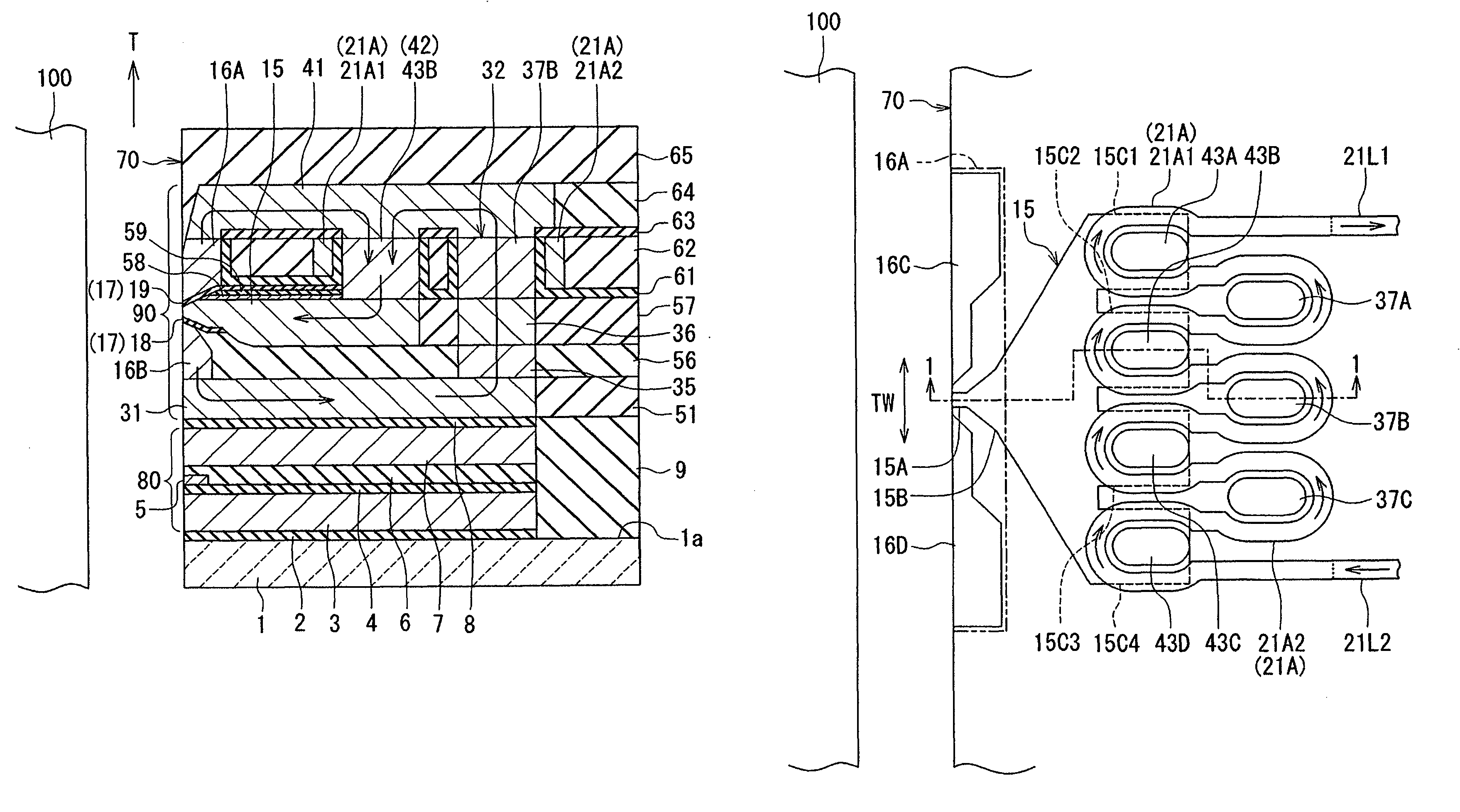
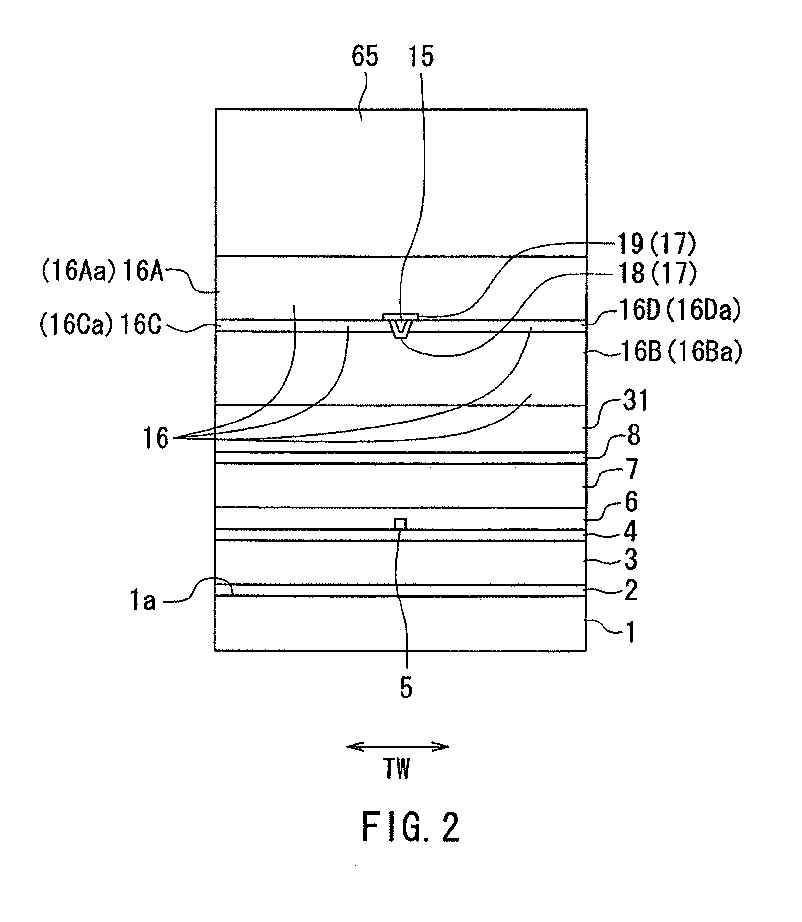
[0042]Preferred embodiments of the present invention will now be described in detail with reference to the drawings. First, reference is made to FIG. 1 to FIG. 3 to describe the configuration of a magnetic head according to a first embodiment of the invention. FIG. 1 is a cross-sectional view showing the magnetic head according to the present embodiment. The arrow with the symbol T in FIG. 1 indicates the direction of travel of a recording medium. The arrows drawn within the magnetic head in FIG. 1 indicate the flows of magnetic flux. FIG. 2 is a front view showing the medium facing surface of the magnetic head according to the present embodiment. FIG. 3 is a plan view showing the main part of the magnetic head according to the present embodiment. FIG. 1 shows a cross section taken at the position indicated by line 1-1 of FIG. 3. In each of FIG. 2 and FIG. 3, the arrow with the symbol TW indicates the track width direction. In FIG. 3, the arrows drawn within the coil indicate the di...

second embodiment

[0099]A magnetic head according to a second embodiment of the invention will now be described with reference to FIG. 4 and FIG. 5. FIG. 4 is a cross-sectional view showing the magnetic head according to the present embodiment. FIG. 5 is a plan view showing the main part of the magnetic head according to the present embodiment. Note that FIG. 4 shows a cross section taken at the position indicated by line 4-4 of FIG. 5.

[0100]The magnetic head according to the present embodiment is different from the magnetic head according to the first embodiment in the following ways. In the magnetic head according to the present embodiment, the main pole 15 includes three branch portions 15C1, 15C2, and 15C3 as the plurality of branch portions. The width of the top surface of each of the branch portions 15C1 to 15C3 in the track width direction TW is generally constant regardless of the distance from the medium facing surface 70, and is smaller than ⅓ the maximum width of the top surface of the mai...

third embodiment

[0104]A magnetic head according to a third embodiment of the invention will now be described with reference to FIG. 6 to FIG. 9. FIG. 6 is a cross-sectional view showing the magnetic head according to the present embodiment. FIG. 7 is a front view showing the medium facing surface of the magnetic head according to the present embodiment. FIG. 8 is a plan view showing a second portion of the coil of the magnetic head according to the present embodiment. FIG. 9 is a plan view showing the main part of the magnetic head according to the present embodiment. Note that FIG. 6 shows a cross section taken at the position indicated by line 6-6 of FIG. 8 and FIG. 9.

[0105]The magnetic head according to the present embodiment is different from the magnetic head according to the second embodiment in the following ways. The magnetic head according to the present embodiment includes magnetic layers 38 and 39 coupling the write shield 16 and the second yoke layer 31 to each other. The magnetic layer...


PUM

PropertyMeasurementUnit
thicknessaaaaaaaaaa
thicknessaaaaaaaaaa
heightaaaaaaaaaa

Abstract

A magnetic head includes a coil, a main pole, a write shield, first and second yoke layers, and first and second coupling parts. The first yoke layer is located on the trailing side relative to the main pole whereas the second yoke layer is located on the leading side relative to the main pole. The first coupling part couples the main pole and the first yoke layer to each other. The second coupling part couples the first yoke layer and the second yoke layer to each other. The first coupling part includes a plurality of first magnetic path portions, and the second coupling part includes a plurality of second magnetic path portions. The coil includes one winding portion extending to pass around the first and second magnetic path portions alternately in a zigzag manner.

Description

BACKGROUND OF THE INVENTION[0001]1. Field of the Invention[0002]The present invention relates to a magnetic head for perpendicular magnetic recording that is used for writing data on a recording medium by means of a perpendicular magnetic recording system, and more specifically, to a magnetic head for perpendicular magnetic recording that has a main pole and a shield.[0003]2. Description of the Related Art[0004]The recording systems of magnetic read / write apparatuses include a longitudinal magnetic recording system wherein signals are magnetized in a direction along the plane of a recording medium (the longitudinal direction) and a perpendicular magnetic recording system wherein signals are magnetized in a direction perpendicular to the plane of a recording medium. It is known that the perpendicular magnetic recording system is harder to be affected by thermal fluctuation of the recording medium and capable of providing higher linear recording density, compared with the longitudinal...

Claims


Application Information

Patent Timeline
Patent Type & Authority Patents(United States)
IPC IPC(8): G11B5/127
CPCG11B5/1278G11B5/3123G11B5/315
Inventor SASAKI, YOSHITAKAITO, HIROYUKISATO, KAZUKITANEMURA, SHIGEKIARAKI, HIRONORISHIMIZU, TATSUYA
Owner HEADWAY TECH INC
Why Eureka
Try Eureka