Inhalation actuated nebulizer with impingement shield

a technology of inhalation actuation and nebulizer, which is applied in the direction of liquid spraying apparatus, spray nozzle, inhalator, etc., to achieve the effect of less mass accumulation, little drying, and little or no residual build-up

Active Publication Date: 2013-12-03
PIPER SAMUEL DAVID
View PDF25 Cites 17 Cited by
  • Summary
  • Abstract
  • Description
  • Claims
  • Application Information

AI Technical Summary

Benefits of technology

[0008]The present invention is directed generally to a nebulizer for the formation of micro-droplets (i.e. aerosol) from liquid medicaments for respiratory patient treatment, and more specifically, to a baffled nebulizer wherein a static baffle used to form an atomized medicament is proximal to a shield which responds to patient respiration force to oscillate from an occluding position to an open flow position. An entrainment orifice within the nebulizer utilizes pressurized gas to draw in liquid medicament from a reservoir and to entrain that liquid medicament into a continuous high velocity stream. The high velocity liquid entrained jet is oriented such that an optimization point is achieved continuously at a defined distance in front of the entrainment orifice. A target surface is positioned at the optimization point of the high velocity jet such that the medicament within the stream is atomized into micro-droplets. When the shield is in a first position, the atomized medicament impinges upon the shield, losing jet momentum, which causes the micro-droplets to coalesce into macro-droplets that are non-respirable and return to the liquid reservoir for re-entrainment. Since the nozzle is continuously entraining and processing medication during this time, although not forming aerosol due the position of the shield, medication is continuously cycled through the nozzle region and there is little drying and little or no residual build up of thick and viscous medications. Thus the invention is less sensitive to mass accumulation and is more able to consistently deliver large molecule, high concentration, and / or more viscous medications. When the shield is in a second position, the micro-droplets are un-occluded and are released into aerosol outlet which then may be inhaled by the patient. The impingement shield moves between the first and second positions based upon the respiration of the patient, thus moving the impingement shield into the second position only when patient inhalation occurs, thereby preventing excessive waste of liquid medicament, improving patient therapy, mitigating the accumulation of medication around the aerosol producing region, mitigating secondary disposable, and doing so in a simple enough manner to lend itself well to a inexpensive and disposable device.
[0010]In a further embodiment of the present invention, the nebulizer assembly is particularly adapted to control atomization in response to patient respiratory forces exceeding a defined threshold. The impingement shield is operably associated with an intake valve such that when a negative threshold pressure is attained within the nebulizer, such as provided by an inhalation force provided by a respiring patient, said intake valve is moved from a closed to an open state establishing inhalation flow through the nebulizer. By rendering the air flow through the nebulizer as contingent upon exceeding a minimum negative pressure it is now possible to constrain atomization of a medicament to the combined operational status of the patient inhaling (to actuate the impingement shield into a second “open” or non-occluding state) and of the patient attaining a defined level of force during inhalation (allowing for opportunity to control inhalation airflow to coincide with deeper pulmonary penetration of medicinal nebula), thus offering enhanced therapy regimes. This combined operational status is particularly noteworthy in that prior art devices will not produce aerosol until there floating baffle is drawn all the way down, which is achieved only upon reaching a minimum inhalation vacuum pressure, the result of which is that it is possible with prior art devices for a patient to breath at a low inhalation flow rate insufficient to draw the floating baffle all the way down so that aerosol is produced. The unique and novel design of the current invention disallows any flow of air through the nebulizer until such time that shield has been drawn down, thus providing greater assurance that aerosol is delivered with each inhalation and being suitable for a broader range of patients. Because the current invention is suitable for a broad range of flow rates, it can be fabricated into a form with a very low nebulization flow rate (e.g. 1.0 l / min) that will maximize its sensitivity to the inhalation effort of the patient.
[0011]In a further embodiment of the present invention, the nebulizer having a respiration responsive impingement shield as presented herein may further include an electronic sensor which is responsive to the position and duration of the impingement shield being in said first and second positions. By using a simple and conventional logic circuit, it is possible to indicate to the patient if insufficient inhalation or exhalation periods of occurred. The same logic circuit can be used to indicate optimum therapy duration to the patient, possible error conditions, or provide estimated dosages by flagging of visual and / or auditory cues. The same logic circuit can be used to transmit the same resulting information through electrically conducting or wireless means to a remote location for use as a clinical evaluation tool or to provide greater management of a patient's condition.

Problems solved by technology

This combined operational status is particularly noteworthy in that prior art devices will not produce aerosol until there floating baffle is drawn all the way down, which is achieved only upon reaching a minimum inhalation vacuum pressure, the result of which is that it is possible with prior art devices for a patient to breath at a low inhalation flow rate insufficient to draw the floating baffle all the way down so that aerosol is produced.

Method used


Image

  • Inhalation actuated nebulizer with impingement shield
  • Inhalation actuated nebulizer with impingement shield
  • Inhalation actuated nebulizer with impingement shield

Examples


example

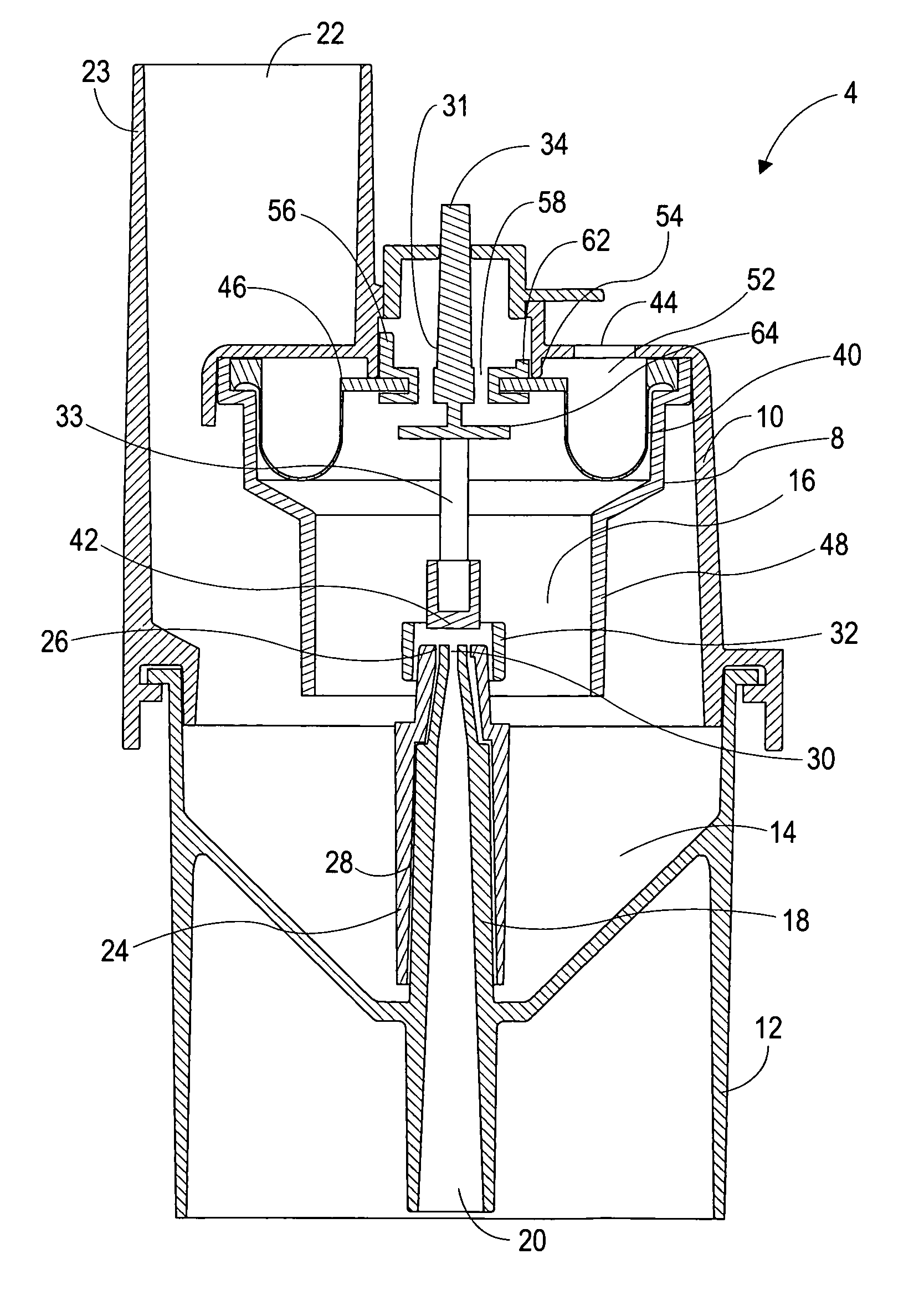
[0051]A first embodiment nebulizer device in accordance with the present invention was fabricated and tested.

[0052]Device Dimensions:

[0053]

Nebulizer Unit height:3.75 inchesNebulizer Unit width / diameter:1.88 inchesShield Assembly Travel Distance:0.17 inchesInhalation port dimensions: 22 mm ISO ID “RespiratoryConduction Mouthpiece”Liquid reservoir maximum volume fill:6.0 millilitersAerosol Outlet Port Diameter:0.90 inches

[0054]In practice with the above example of a preferred embodiment, nebulizer unit 4 is supplied gas to inlet port 20 at a pressure of at least 8 psig, and more preferably at least 13 psig, at a flow rate of between 1 and 15 liters of gas per minute, with the range of 5 to 12 liters per minute inclusively being preferred and the range of 8 to 11 liters per minute inclusively being most preferred. The gas issues through a jet orifice having a diameter in the range of 0.011 to 0.030 inches, and more preferably in the range of 0.019 to 0.026 inches. The ratio of the cros...


PUM


Abstract

The present invention is directed generally to a nebulizer for the formation of micro-droplets from liquid medicaments for respiratory patient treatment, and more specifically, to a baffled nebulizer wherein a static baffle used to form an atomized medicament is proximal to a shied which responds to patient respiration force to oscillate from an aerosol flow occluding position to an aerosol flow open position. During inhalation, the shield moves into a first registration format to allow passage of the atomized medicament (nebula) to the patient. During exhalation / non-use, a biasing pressure maintains said shield in a second registration format such that the nebula is retarded from passing to the patient and is coalesced into macro-droplets which return to a supply reservoir for re-atomization. The present nebulizer design is particularly adaptable for controlling atomization in response to patient respiratory forces exceeding a defined threshold; allowing for opportunity to control inhalation airflow and enhanced therapy regimes.

Description

CROSS-REFERENCE TO RELATED APPLICATIONS[0001]This application claims the benefit under 35 U.S.C. 119(e) of U.S. provisional application Ser. No. 61 / 281,402 filed Nov. 16, 2009, which is incorporated by reference herein in its entiretySTATEMENT REGARDING FEDERALLY SPONSORED RESEARCH[0002]Not ApplicableBACKGROUND OF THE INVENTION[0003]Nebulizers for producing micro-droplets (i.e. aerosol) from liquid medicaments and presenting those aerosols for patient respiratory therapy are a well-known and practiced technology. A typical nebulizer design includes the basic elements of a gas inlet port, a respirable gas outlet, a liquid reservoir and a means for forming micro-droplets of the liquid within the reservoir. Early designs, such as represented by U.S. Pat. No. 3,097,645 and U.S. Pat. No. 3,762,409, both to Lester and incorporated by reference in their entireties herein, depict the basic elements of a typical constant-flow type nebulizer. Constant-flow type nebulizers create micro-droplet...

Claims


Application Information

Patent Timeline
Patent Type & Authority Patents(United States)
IPC IPC(8): B05B1/26A61M11/00
CPCA61M11/06A61M15/0091A61M16/0833A61M16/20A61M15/0021A61M15/0093A61M16/1065A61M16/206A61M11/002A61M16/208B05B7/0433A61M15/008A61M15/0098
Inventor PIPER, SAMUEL DAVID
Owner PIPER SAMUEL DAVID
Why Eureka
Try Eureka