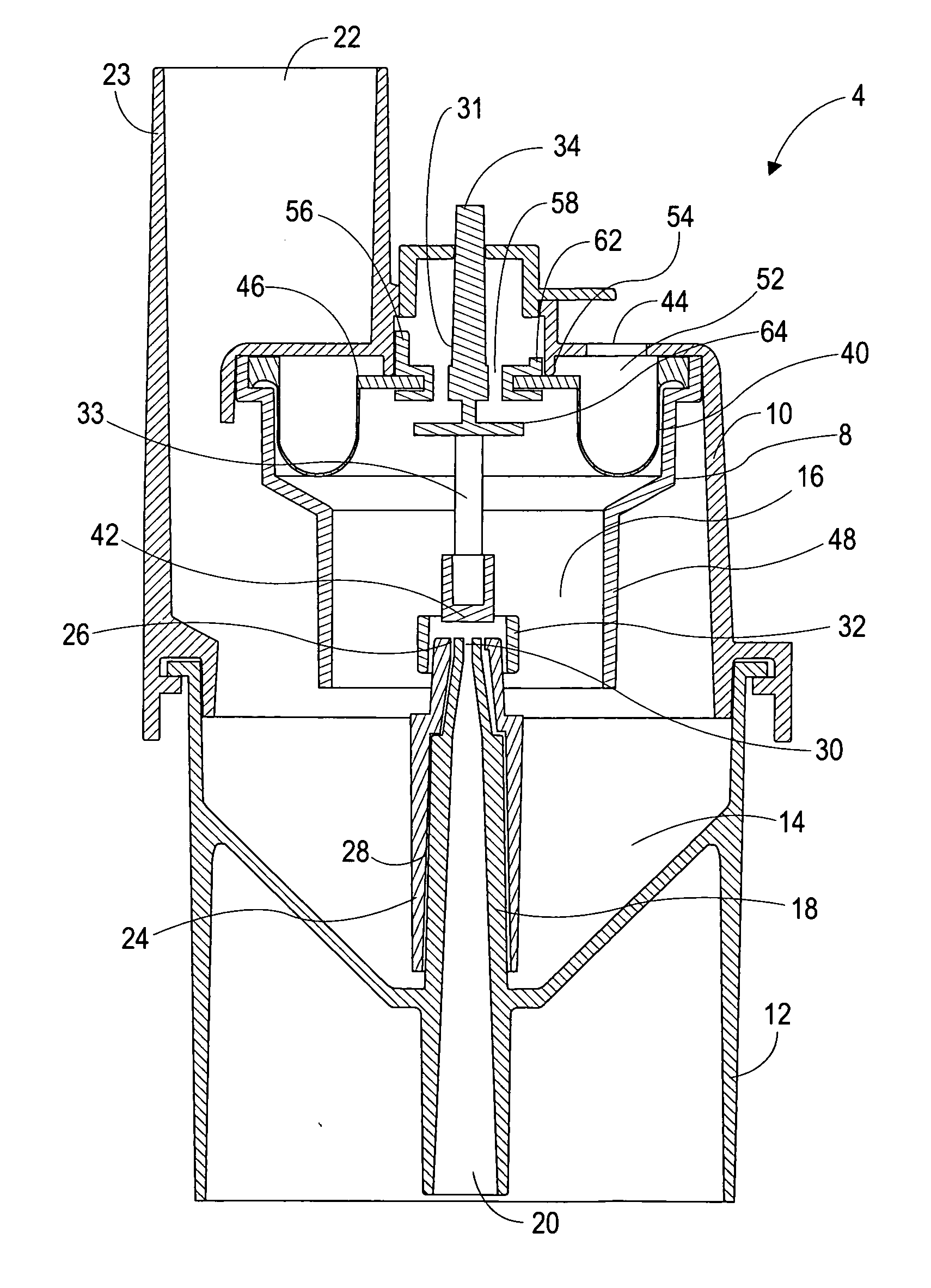
[0008]The present invention is directed generally to a nebulizer for the formation of micro-droplets (i.e. aerosol) from liquid medicaments for respiratory
patient treatment, and more specifically, to a baffled nebulizer wherein a static baffle used to form an atomized medicament is proximal to a shield which responds to patient
respiration force to oscillate from an occluding position to an open flow position. An entrainment orifice within the nebulizer utilizes pressurized gas to draw in liquid medicament from a reservoir and to entrain that liquid medicament into a continuous
high velocity stream. The
high velocity liquid entrained jet is oriented such that an optimization point is achieved continuously at a defined distance in front of the entrainment orifice. A
target surface is positioned at the optimization point of the
high velocity jet such that the medicament within the
stream is atomized into micro-droplets. When the shield is in a first position, the atomized medicament impinges upon the shield, losing jet
momentum, which causes the micro-droplets to coalesce into
macro-droplets that are non-respirable and return to the liquid reservoir for re-entrainment. Since the
nozzle is continuously entraining and
processing medication during this time, although not forming aerosol due the position of the shield, medication is continuously cycled through the
nozzle region and there is little
drying and little or no residual build up of thick and viscous medications. Thus the invention is less sensitive to
mass accumulation and is more able to consistently deliver large molecule,
high concentration, and / or more viscous medications. When the shield is in a second position, the micro-droplets are un-occluded and are released into aerosol outlet which then may be inhaled by the patient. The impingement shield moves between the first and second positions based upon the
respiration of the patient, thus moving the impingement shield into the second position only when patient inhalation occurs, thereby preventing excessive waste of liquid medicament, improving patient therapy, mitigating the accumulation of medication around the aerosol producing region, mitigating secondary disposable, and doing so in a simple enough manner to lend itself well to a inexpensive and disposable device.
[0010]In a further embodiment of the present invention, the nebulizer
assembly is particularly adapted to control atomization in response to patient respiratory forces exceeding a defined threshold. The impingement shield is operably associated with an intake valve such that when a negative threshold pressure is attained within the nebulizer, such as provided by an inhalation force provided by a respiring patient, said intake valve is moved from a closed to an open state establishing inhalation flow through the nebulizer. By rendering the air flow through the nebulizer as contingent upon exceeding a minimum negative pressure it is now possible to constrain atomization of a medicament to the combined operational status of the patient inhaling (to actuate the impingement shield into a second “open” or non-occluding state) and of the patient attaining a defined level of force during inhalation (allowing for opportunity to control inhalation
airflow to coincide with deeper pulmonary penetration of medicinal nebula), thus offering enhanced therapy regimes. This combined operational status is particularly noteworthy in that prior art devices will not produce aerosol until there floating baffle is drawn all the way down, which is achieved only upon reaching a minimum inhalation
vacuum pressure, the result of which is that it is possible with prior art devices for a patient to breath at a low inhalation flow rate insufficient to draw the floating baffle all the way down so that aerosol is produced. The unique and novel design of the current invention disallows any flow of air through the nebulizer until such time that shield has been drawn down, thus providing greater assurance that aerosol is delivered with each inhalation and being suitable for a broader range of patients. Because the current invention is suitable for a broad range of flow rates, it can be fabricated into a form with a very low nebulization flow rate (e.g. 1.0 l / min) that will maximize its sensitivity to the inhalation effort of the patient.
[0011]In a further embodiment of the present invention, the nebulizer having a respiration responsive impingement shield as presented herein may further include an electronic sensor which is responsive to the position and duration of the impingement shield being in said first and second positions. By using a simple and conventional logic circuit, it is possible to indicate to the patient if insufficient inhalation or
exhalation periods of occurred. The same logic circuit can be used to indicate optimum therapy duration to the patient, possible error conditions, or provide estimated dosages by
flagging of visual and / or auditory cues. The same logic circuit can be used to transmit the same resulting information through electrically conducting or
wireless means to a remote location for use as a
clinical evaluation tool or to provide greater management of a patient's condition.

