Single field rotor motor

Inactive Publication Date: 2007-03-22
TRI SEVEN RES
View PDF7 Cites 1 Cited by
  • Summary
  • Abstract
  • Description
  • Claims
  • Application Information

AI Technical Summary

Benefits of technology

[0003] It is known that if the area within an electric motor where the alternating flux used in the motor stator is kept small, increased efficiency will be experienced, as there is less metal mass involved i

Problems solved by technology

Reversing flux fields are created in conventional electric motor devices, and because of the necessity to overcome non-work flux fields, the efficiency of the motor is adversely affected.
Over the years, various structural and theoretical systems have been produced in the electric motor art

Method used


Image

  • Single field rotor motor
  • Single field rotor motor
  • Single field rotor motor

Examples


Embodiment Construction

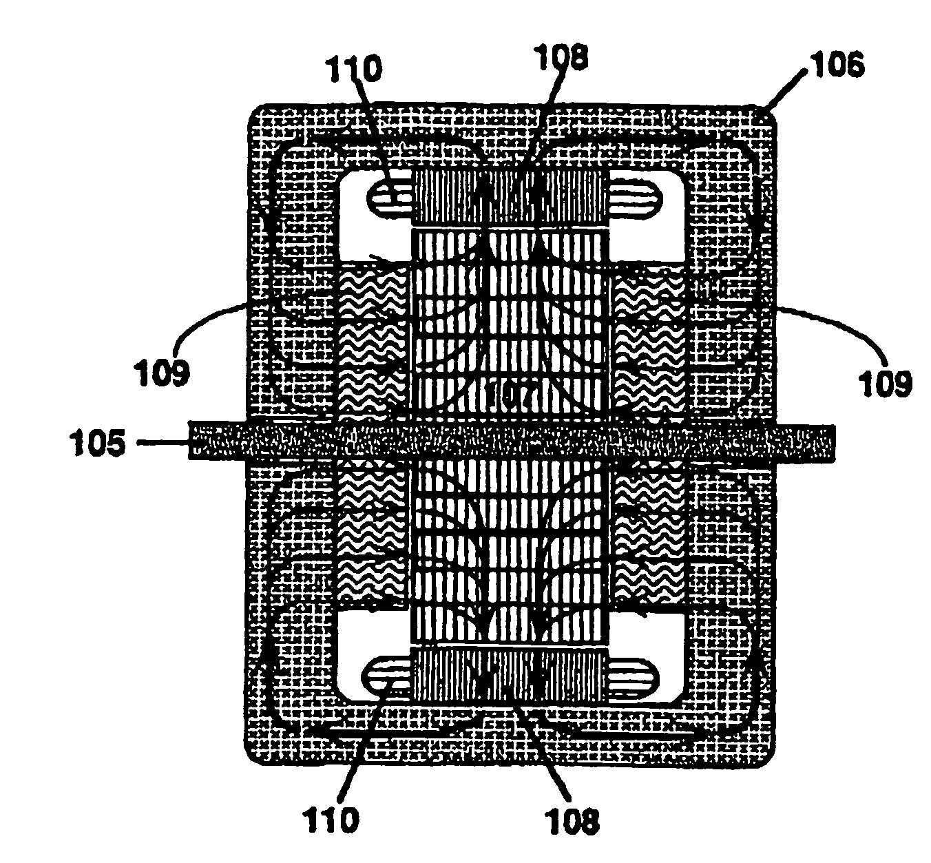
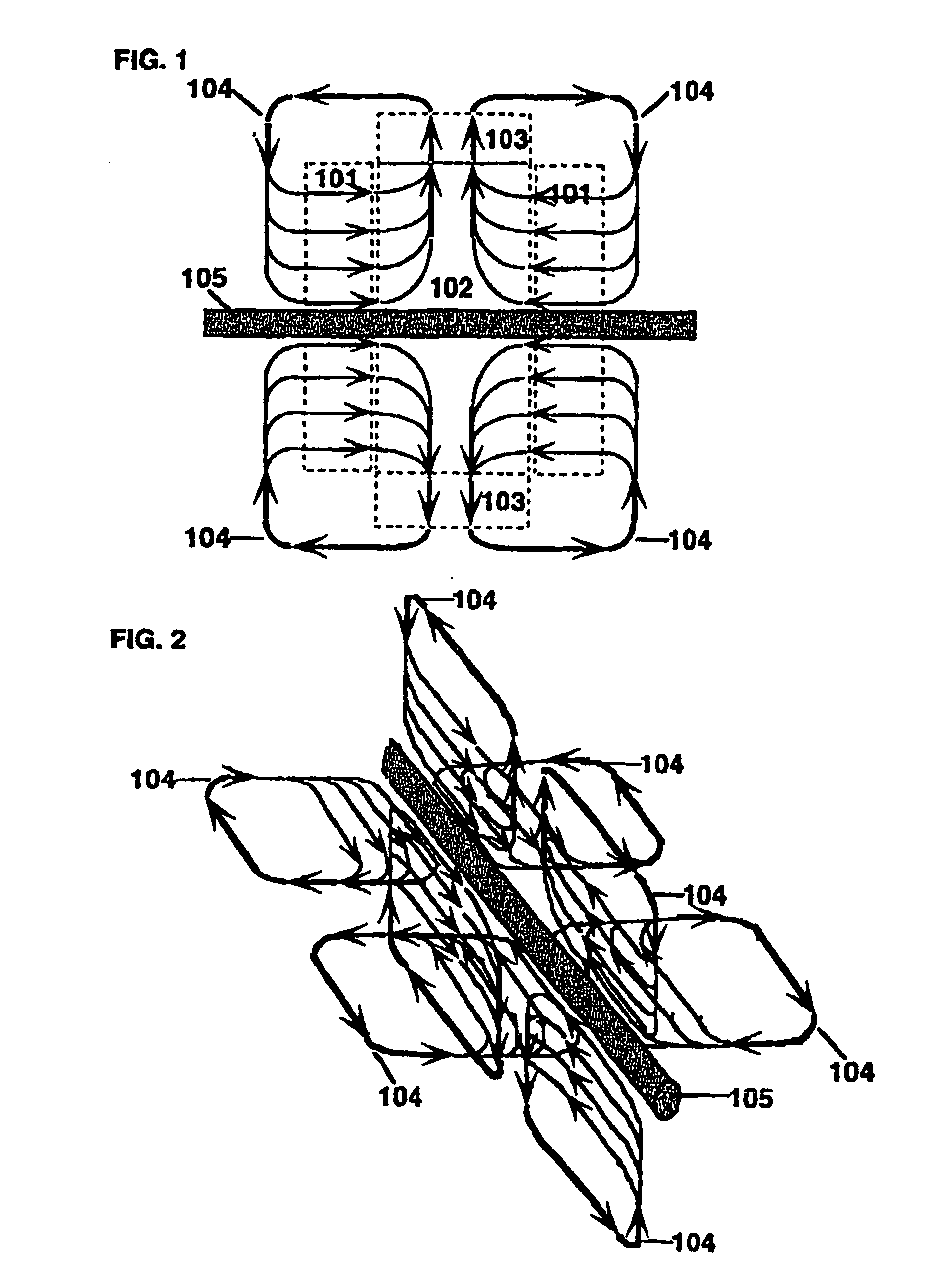
[0039]FIG. 1 schematically illustrates the configuration and paths of the primary torque flux in the single field rotor motor in accord with the invention regardless of whether the flux is created by permanent magnets or DC coils and cores of the stator. The areas illustrated and enclosed by dotted lines 101 is the area where the flux originates in the magnets or DC coil cores. The area in dotted line box 102 is the rotor-torque area of the motor where the rotor rotates and illustrates how the opposing polarity of the flux entering the rotor-torque area from opposite sides causes it to spray perpendicular to the motor axis. The rotor's laminations also are oriented perpendicular to the axis which further encourages this effect, and the laminations of the rotor become the ferrite path for the flux to travel to the circumference of the rotor where the rotor poles are formed. Areas 103 represent the areas of the stator which is laminated with poles and wound with phase coils and illust...


PUM


Abstract

An electric motor having a single field rotor wherein the flux within the rotor is generated by magnetic means located at the end regions of the motor housing such that the flux within the motor rotor maintains a constant polarity.

Description

FIELD OF THE INVENTION [0001] The invention pertains to a single field rotor motor wherein a minimum of alternating flux fields in the total flux circuit of the motor that produces the motor torque are created. The result is that the creation of a non-reversing flux field in a major portion of the stator and rotor parts creates less losses and produces greater efficiency in the overall motor operation. DESCRIPTION OF THE RELATED ART [0002] In typical electric motor construction and theory, alternating flux fields are created, and various systems are utilized to unbalance these flux fields so that a rotation of the motor rotor would occur. Reversing flux fields are created in conventional electric motor devices, and because of the necessity to overcome non-work flux fields, the efficiency of the motor is adversely affected. Over the years, various structural and theoretical systems have been produced in the electric motor art to overcome such conventional inefficiencies, but heretofo...

Claims


Application Information

Patent Timeline
IPC IPC(8): H02K17/00H02K31/00H02K1/12H02K1/24H02K19/10H02K21/38
CPCH02K21/44H02K19/103
Inventor DURHAM, GARY L.DURHAM, HAROLD S.
Owner TRI SEVEN RES
Why Eureka
Try Eureka