Variable resistance fitness chamber for rotational torque

a fitness chamber and rotational torque technology, applied in the direction of frictional force resistors, gymnastic exercise, couplings, etc., can solve the problems of creating “reactive force” in the side effect, causing injury to the user, and intimidating the would-be exerciser

Inactive Publication Date: 2013-12-10
MORRIS NICHOLAS
View PDF16 Cites 56 Cited by
  • Summary
  • Abstract
  • Description
  • Claims
  • Application Information

AI Technical Summary

Problems solved by technology

However, many would be exercisers are intimidated by complex fitness machines and uncomfortable and unnatural motions associated with exercising.
In addition, they may be reluctant to use heavy weights which can cause injury to the user.
However, this creates the side effect of creating “reactive-force”.
Reactive force can cause damage to the user's body if the resistance is too strong for a user and the exercise movement becomes uncontrolled.
Further, reactive force is a dissipated energy, and means a less than optimal result to the exerciser, meaning a poor return on time and effort invested in the exercise.
This does not allow the exercise system to be used by individuals of different fitness levels.
In particular, some individuals will be too new to exercising to use the exercise system while other individuals will be too advanced.
In addition, elastic materials can rebound if the material fails.
When the material fails the force in the material can cause sudden and unpredictable movement, which has potential to injure the user or damage the equipment.
This is an inherent danger of the materials and the ability to reduce or eliminate this danger is very limited.
Further, many exercise systems use unnatural movements.
These unnatural movements can cause injury to the user.
Often, the user will not even be aware of the injury until it becomes a major injury because they don't perform that movement unless exercising.

Method used


Image

  • Variable resistance fitness chamber for rotational torque
  • Variable resistance fitness chamber for rotational torque
  • Variable resistance fitness chamber for rotational torque

Examples


Embodiment Construction

[0019]This Summary is provided to introduce a selection of concepts in a simplified form that are further described below in the Detailed Description. This Summary is not intended to identify key features or essential characteristics of the claimed subject matter, nor is it intended to be used as an aid in determining the scope of the claimed subject matter.

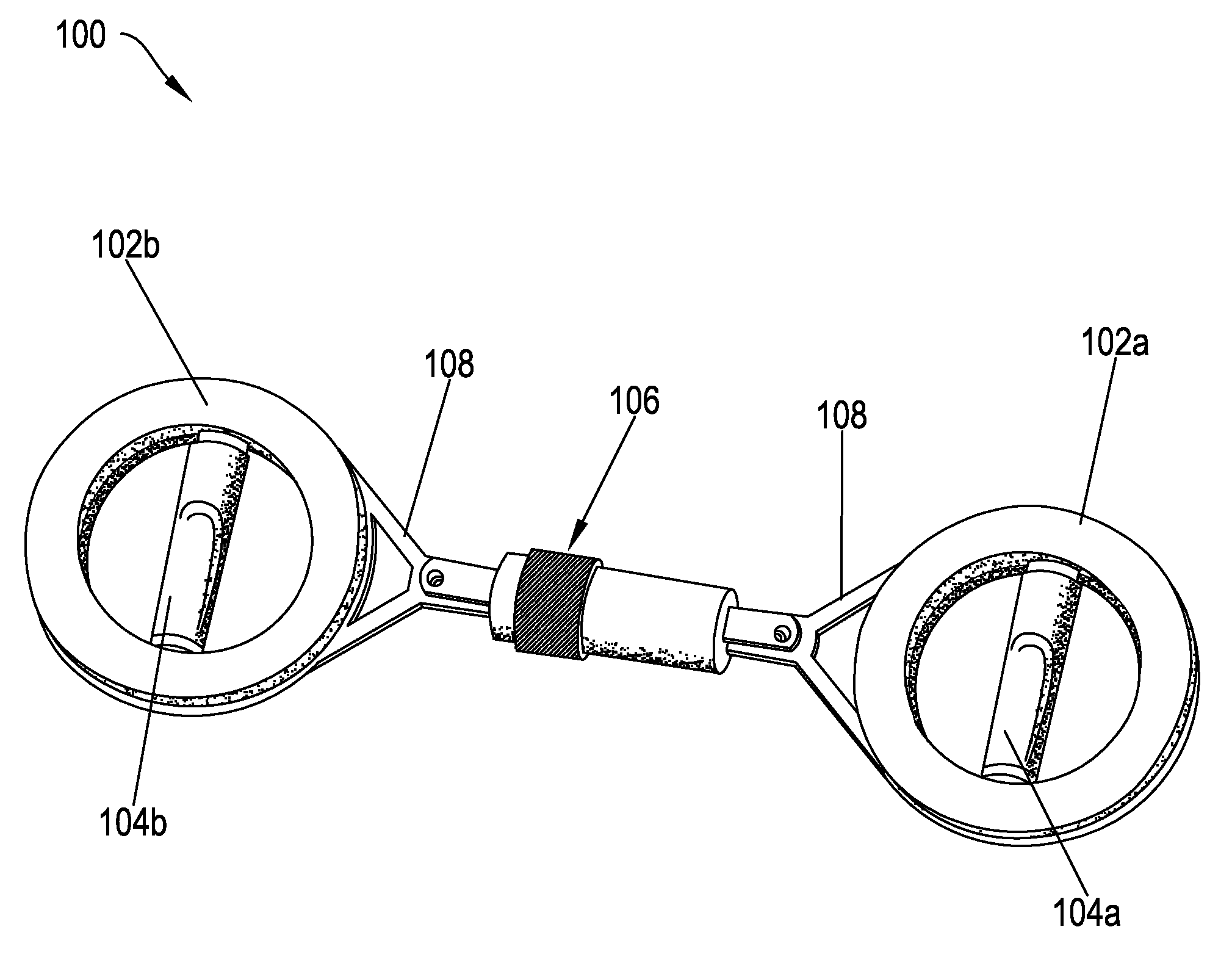
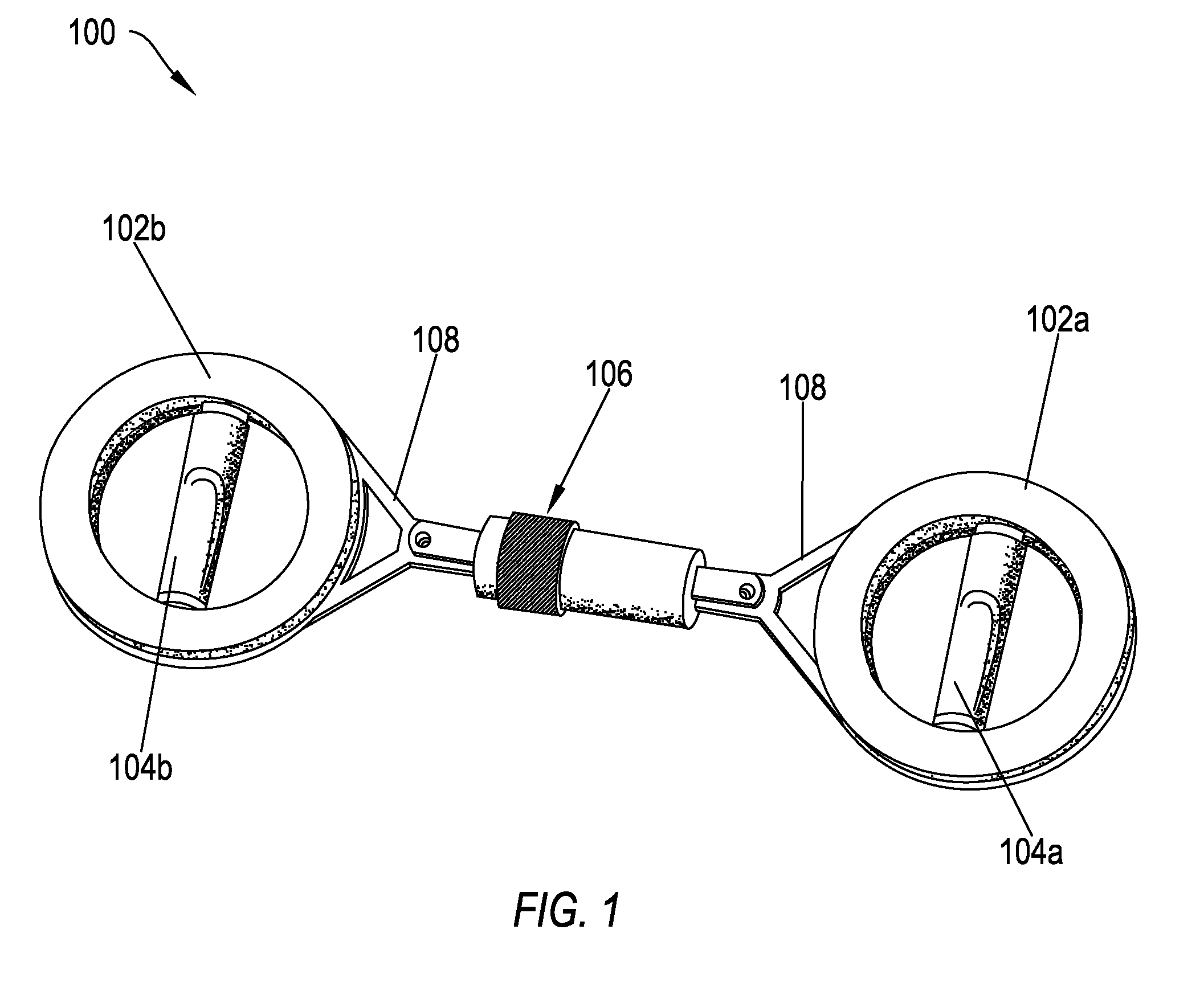
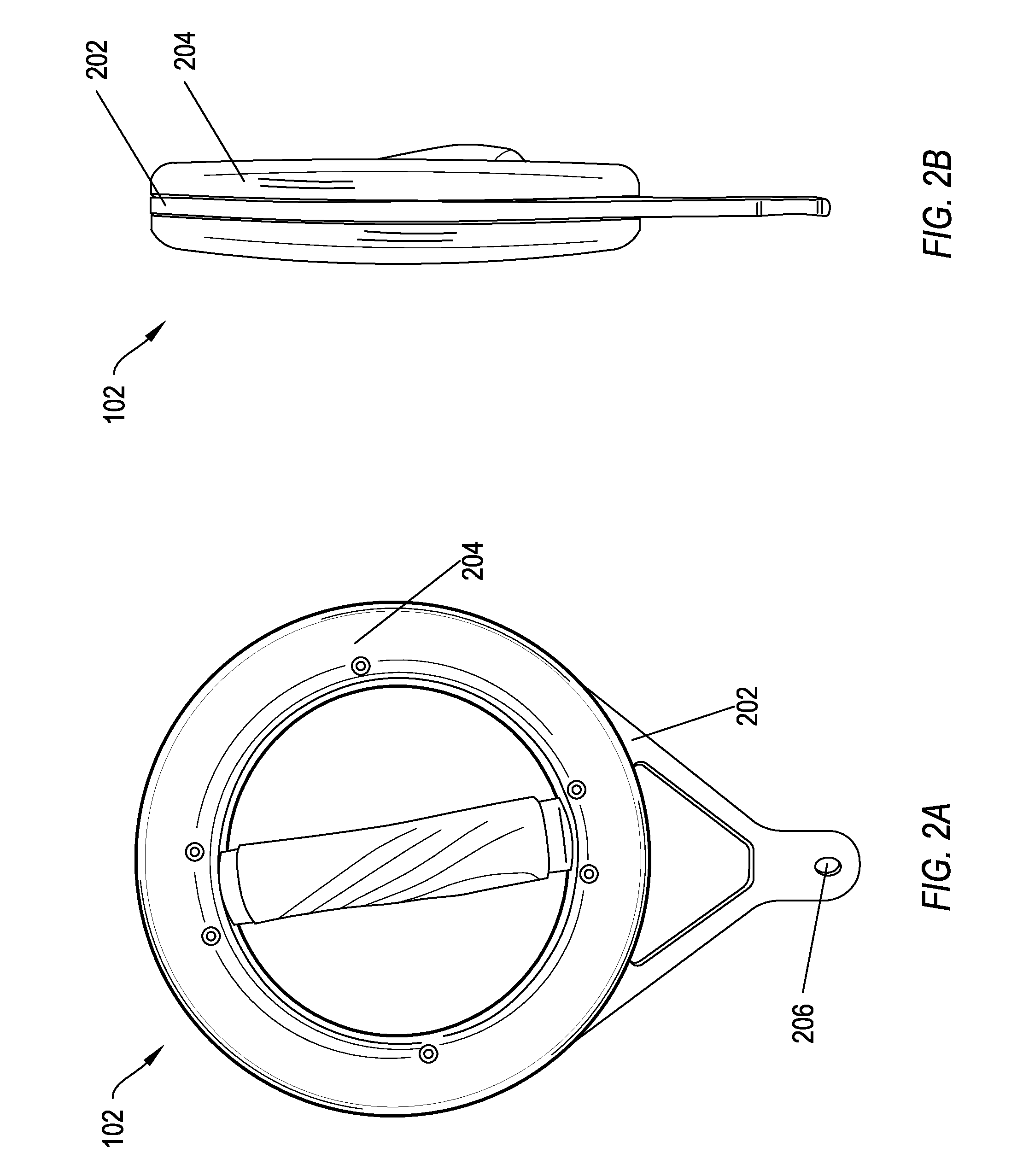
[0020]One example embodiment includes a resistance chamber for use in an exercise system. The resistance chamber includes a first chamber and a second chamber. The second chamber is configured to attach to the first chamber and rotate relative to the first chamber. The resistance chamber also includes a core rod. The core rod resides within the first chamber and the second chamber and is attached to the interior of the second chamber. The resistance chamber further includes a resistance tube, where at least of a portion the resistance tube is configured to be placed between the interior surface of the first chamber and the core r...


PUM

PropertyMeasurementUnit
resistanceaaaaaaaaaa
RESISTANCEaaaaaaaaaa
ROTATION RESISTANCEaaaaaaaaaa

Abstract

One example embodiment includes a resistance chamber for use in an exercise system. The resistance chamber includes a first chamber and a second chamber. The second chamber is configured to attach to the first chamber and rotate relative to the first chamber. The resistance chamber also includes a core rod. The core rod resides within the first chamber and the second chamber and is attached to the interior of the second chamber. The resistance chamber further includes a resistance tube, where at least of a portion the resistance tube is configured to be placed between the interior surface of the first chamber and the core rod.

Description

CROSS-REFERENCE TO RELATED APPLICATIONS[0001]This application claims the benefit of and priority to U.S. Provisional Patent Application Ser. No. 61 / 395,784 filed on May 17, 2010, which application is incorporated herein by reference in its entirety.[0002]This application is related to co-pending U.S. application Ser. No. 13 / 109,654, filed on May 17, 2011, and entitled, “BALL NEST WITH VARIABLE RESISTANCE FOR FITNESS AND WELLNESS MOVEMENT”, which application is incorporated herein by reference in its entirety.[0003]Co-pending U.S. application Ser. No. 13 / 109,654, filed on May 17, 2011, and entitled, “BALL NEST WITH VARIABLE RESISTANCE FOR FITNESS AND WELLNESS MOVEMENT” claims the benefit of and priority to U.S. Provisional Patent Application Ser. No. 61 / 395,823 filed on May 17, 2010, which application is incorporated herein by reference in its entirety.[0004]This application is related to co-pending U.S. application Ser. No. 13 / 109,654, filed on May 17, 2011, and entitled, “VERTICAL ...

Claims


Application Information

Patent Timeline
Patent Type & Authority Patents(United States)
IPC IPC(8): A63B23/00A63B23/12A63B23/14A63B23/035A63B21/00A63B21/02A63B21/045F16F1/36F16F1/38
CPCA63B21/0004A63B21/00069A63B21/00185A63B21/015A63B21/0601A63B21/1496A63B23/12A63B21/00043A63B23/03533A63B21/4035A63B21/4045A63B21/4049Y10T403/40Y10T403/405Y10T403/45Y10T403/455
Inventor MORRIS, NICHOLAS
Owner MORRIS NICHOLAS
Why Eureka
Try Eureka