Method and apparatus for determining the proximity of a TMS coil to a subject's head

a proximity measurement and proximity technology, applied in the field of proximity measurement and contact positioning apparatus, can solve the problems of severe clinical limitations, unfavorable clinical use, and high cost of three-dimensional spatial methods based on imaging modalities, and achieve the effect of reducing the amplitude of the sound

Active Publication Date: 2005-10-20
NEURONETICS
View PDF93 Cites 100 Cited by
  • Summary
  • Abstract
  • Description
  • Claims
  • Application Information

AI Technical Summary

Benefits of technology

[0012] In a fifth embodiment, the sensors may comprise an acoustic device that produces an acoustic sound (that may or may not be in the human audible range) when a TMS coil of the TMS coil assembly is pulsed and reduces an amplitude of the sound as the acoustic device is compressed by the TMS coil assembly against the position. Acoustic sensors detect the s

Problems solved by technology

These techniques have severe clinical limitations.
The manual methods do not provide a convenient means for repeated and accurate placement, while the three dimensional spatial methods based on imaging modalities are expensive, time consuming, and not conducive to clinical use.
The clinician does not currently have a good method to ensure that the coil is in contact, and has no means of feedback as to whether the coil has moved away from the scalp during treatment.
If the coil movement occurs during the motor threshold (MT) level determination procedure, an inappropriately high power setting may be used.
On the other hand, if the movement occurs after MT determination and during the treatment session, an inappropriately low magnetic field may be applied to the patient resulting i

Method used


Image

  • Method and apparatus for determining the proximity of a TMS coil to a subject's head
  • Method and apparatus for determining the proximity of a TMS coil to a subject's head
  • Method and apparatus for determining the proximity of a TMS coil to a subject's head

Examples


Embodiment Construction

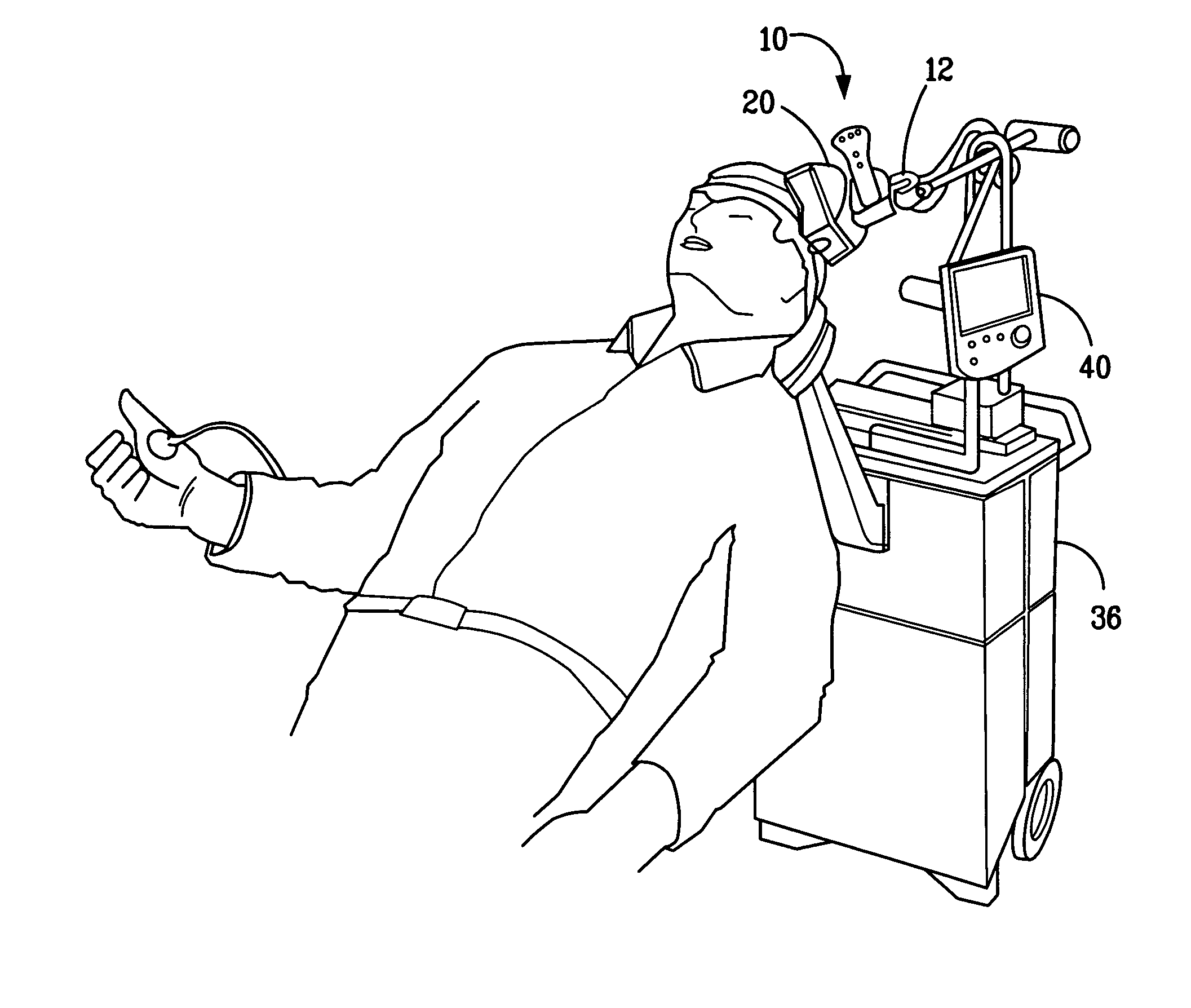
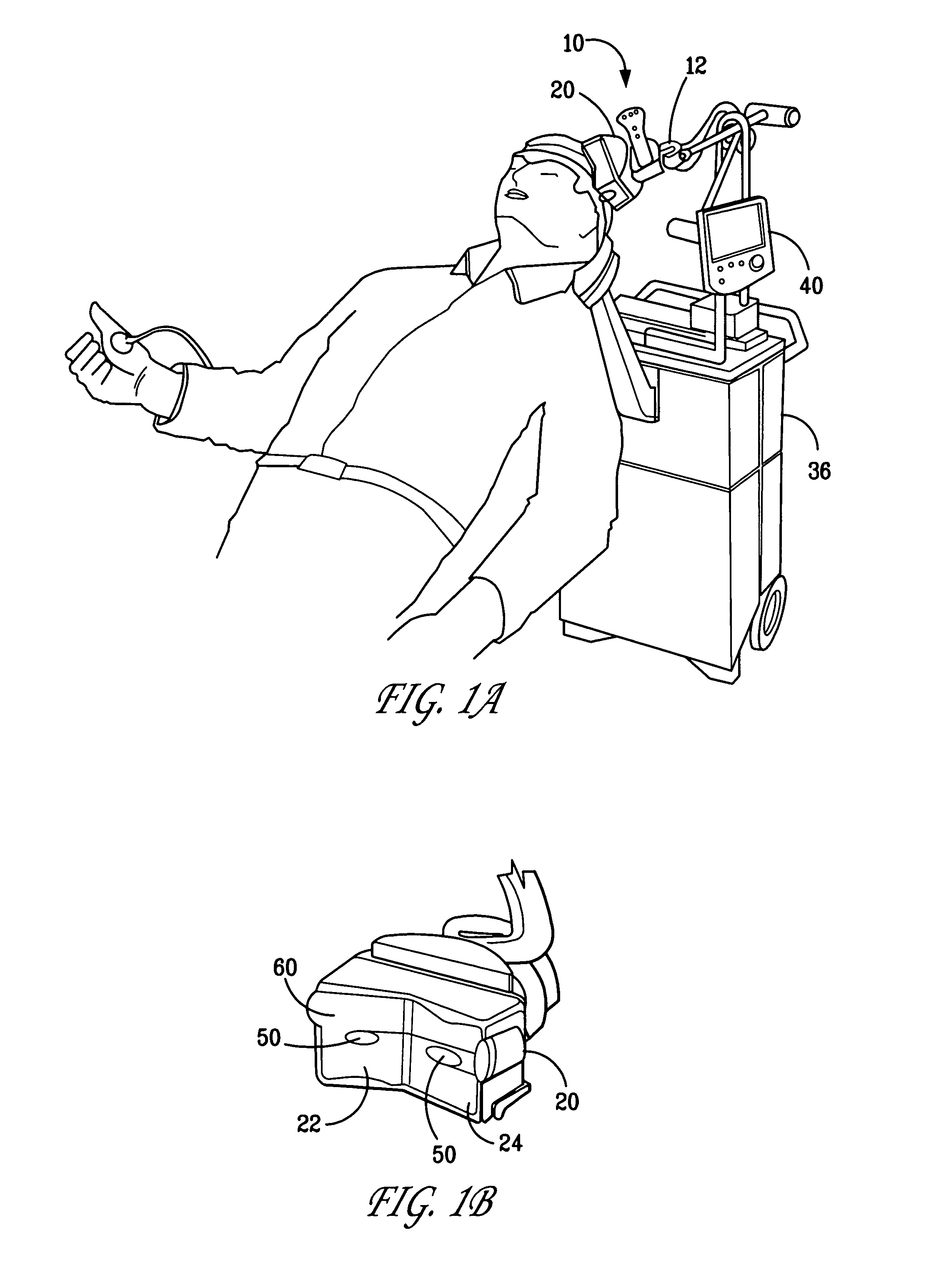
[0047] A detailed description of an illustrative embodiment of the present invention will now be described with reference to FIGS. 1-18. Although this description provides detailed examples of possible implementations of the present invention, it should be noted that these details are intended to be exemplary and in no way delimit the scope of the invention.

[0048] The present invention is designed to sense the positioning of a TMS coil used for treatment of central nervous system disease states using TMS therapies. While an exemplary embodiment of the invention is described with respect to the excitatory stimulation of the left prefrontal cortex for the treatment of depression, those skilled in the art will appreciate that the apparatus and techniques of the invention may be used to apply TMS therapies to many other central nervous system targets for the treatment of numerous other central nervous system diseases. For example, the TMS coil position sensing device of the invention m...


PUM


Abstract

A proximity sensor for a transcranial magnetic stimulation (TMS) system detects the proximity of a TMS coil assembly to a position at which the coil is to receive pulses during TMS treatment and provides feedback to the operator so that the operator may adjust the TMS coil assembly as necessary to maintain optimal positioning during treatment. A flexible substrate containing a sensor or sensor array is disposed between the TMS coil assembly and the position such that the coupling of the TMS coil assembly to the position may be detected by the sensor(s). Sensor outputs are processed by signal processing circuitry to provide an indication of whether the TMS coil assembly is properly disposed with respect to the position during TMS treatment. A display may be used to provide an indication of how to adjust the TMS coil assembly to improve the positioning of the TMS coil assembly. On the other hand, a sound generator may be used to generate a sound that indicates to an operator whether the TMS coil assembly is properly positioned at the position. Many different types of sensor devices may be used to detect proximity, including membrane switches, variable resistance sensors, resistive strips, touch screens, pickup loops, fluid displacement sensors, optical sensors, acoustic sensors, inductive coupling sensors, capacitive coupling sensors, temperature sensors, and the like.

Description

FIELD OF THE INVENTION [0001] The present invention relates to a method and apparatus for determining the proximity of a TMS treatment coil to a position on a patient and, more particularly, to a proximity measurement and contact positioning apparatus and method for determining whether a TMS coil is properly seated against a patient's head during treatment. BACKGROUND OF THE INVENTION [0002] Current methods of placement and positioning of coils for Transcranial Magnetic Stimulation (TMS) studies are either manual methods or approaches designed for research that require expensive and complex imaging or computational systems to determine three dimensional spatial coordinates for positioning reference. These techniques have severe clinical limitations. The manual methods do not provide a convenient means for repeated and accurate placement, while the three dimensional spatial methods based on imaging modalities are expensive, time consuming, and not conducive to clinical use. According...

Claims


Application Information

Patent Timeline
IPC IPC(8): A61B17/52A61N2/00A61N2/02
CPCA61B2019/465A61N2/02A61N2/006A61B2090/065A61B5/05A61B5/6835A61B5/684A61B5/6843A61B5/6844A61B2562/0257A61B2562/164
Inventor RIEHL, MARK EDWARDGHIRON, KENNETH MARCMILLER, STANFORD W.
Owner NEURONETICS
Why Eureka
Try Eureka