Image forming apparatus with turnable image reading part and suspending mechanism

a technology of turning support points and forming apparatuses, which is applied in the direction of digital output to print units, instruments, digitally marking record carriers, etc., can solve the problems of limited apparatus configuration, increased cost, and also safety problems, and achieves simple configuration, improved opening and closing performance of outer covers, and not affecting the downsizing of the main body of the apparatus

Active Publication Date: 2013-12-10
KYOCERA DOCUMENT SOLUTIONS INC
View PDF11 Cites 6 Cited by
  • Summary
  • Abstract
  • Description
  • Claims
  • Application Information

AI Technical Summary

Benefits of technology

[0013]In view of the problems described above, it is an object of the present invention to provide an image forming apparatus which can improve opening and closing performance of an outer cover with simple configuration, requires a small number of components, and also does not impair downsizing of an apparatus main body and a secondary external view of the apparatus, without leading to apparatus upsizing and operability deterioration.

Problems solved by technology

However, with the method of loading the image reading part at the opening and closing cover on the top surface of the apparatus and then opening the opening and closing cover together with the image reading part, turning support points of the image reading part and the opening and closing cover are the same, which therefore requires arrangement of the image reading part and the opening and closing cover in a superimposed manner, resulting in limited configuration of the apparatus.
Providing a large open angle of the opening and closing cover inevitably results in a large open angle of the image reading part, but providing the large open angle of the image reading part that weighs much results in great load imposed on the turning support points.
This therefore requires configuration of the turning support points that can bear the load, which leads to a cost increase and also a safety problem.
With the method of opening the top cover capable of opening and closing by turning after turning upward the turnable reading and loading base loaded with the image reading part, the reading and loading base and the top cover need to be turned sequentially, which results in an increase in procedures at time of cartridge replacement, leading to a problem that replacement operation is troublesome.
Described here is, as an example, the configuration such that the cartridge is arranged immediately below the outer cover, but the same problem arises for maintenability in a case where a different unit is arranged immediately below the outer cover.
Further, not only with the xerographic type but also with, for example, an ink-jet type, in a case where the image reading part is set above the apparatus main body, there is possibility that maintenability in, for example, ink cartridge replacement deteriorates.
However, to open and close the outer wall member in conjunction with the opening and closing operation of the image reading part, a plurality of link members for holding open postures of the image reading part and the outer wall member are required, which results in complication due to an increase in the number of components, thereby leading to a problem that the apparatus main body becomes large-sized.

Method used


Image

  • Image forming apparatus with turnable image reading part and suspending mechanism
  • Image forming apparatus with turnable image reading part and suspending mechanism
  • Image forming apparatus with turnable image reading part and suspending mechanism

Examples


Embodiment Construction

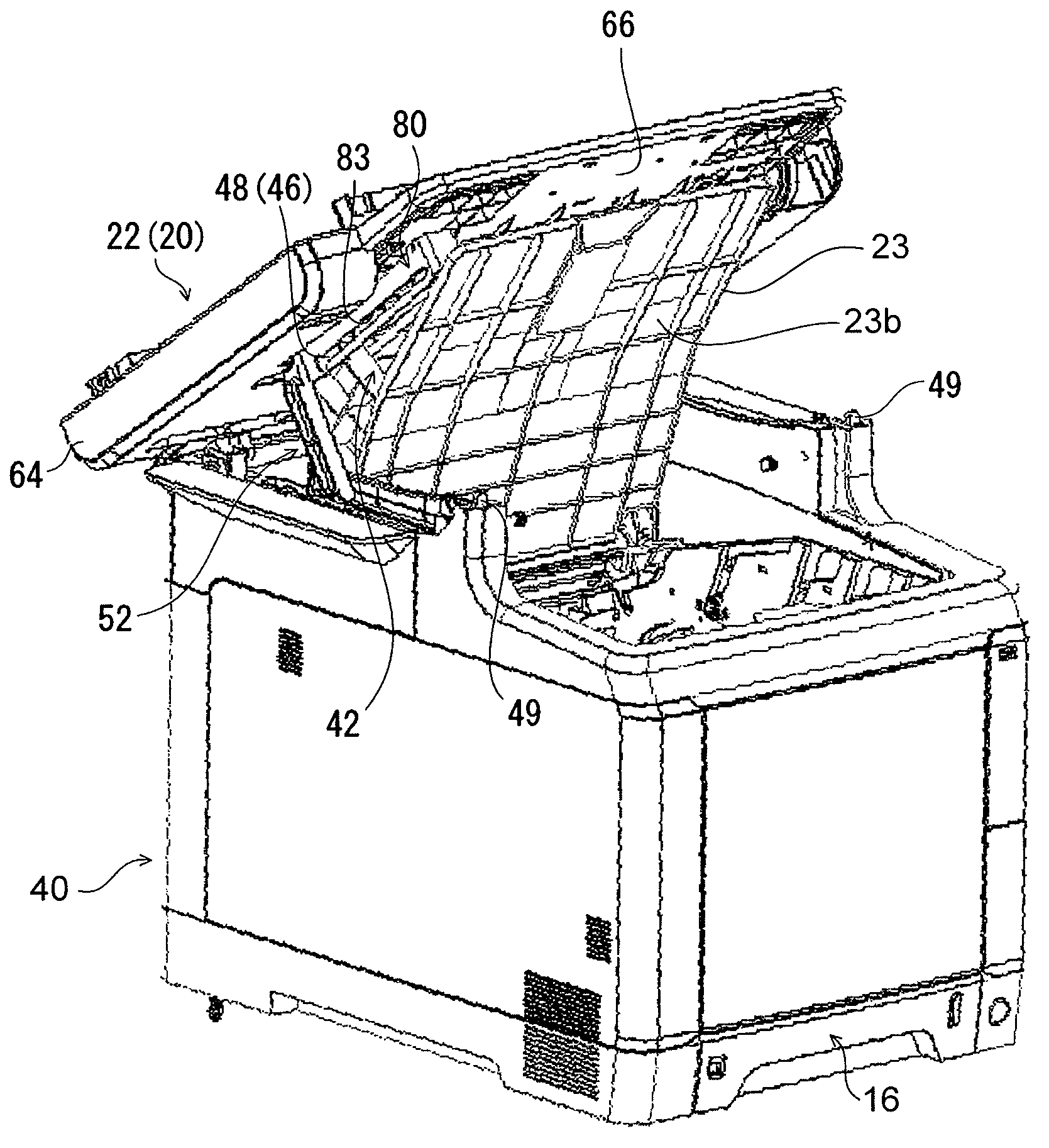
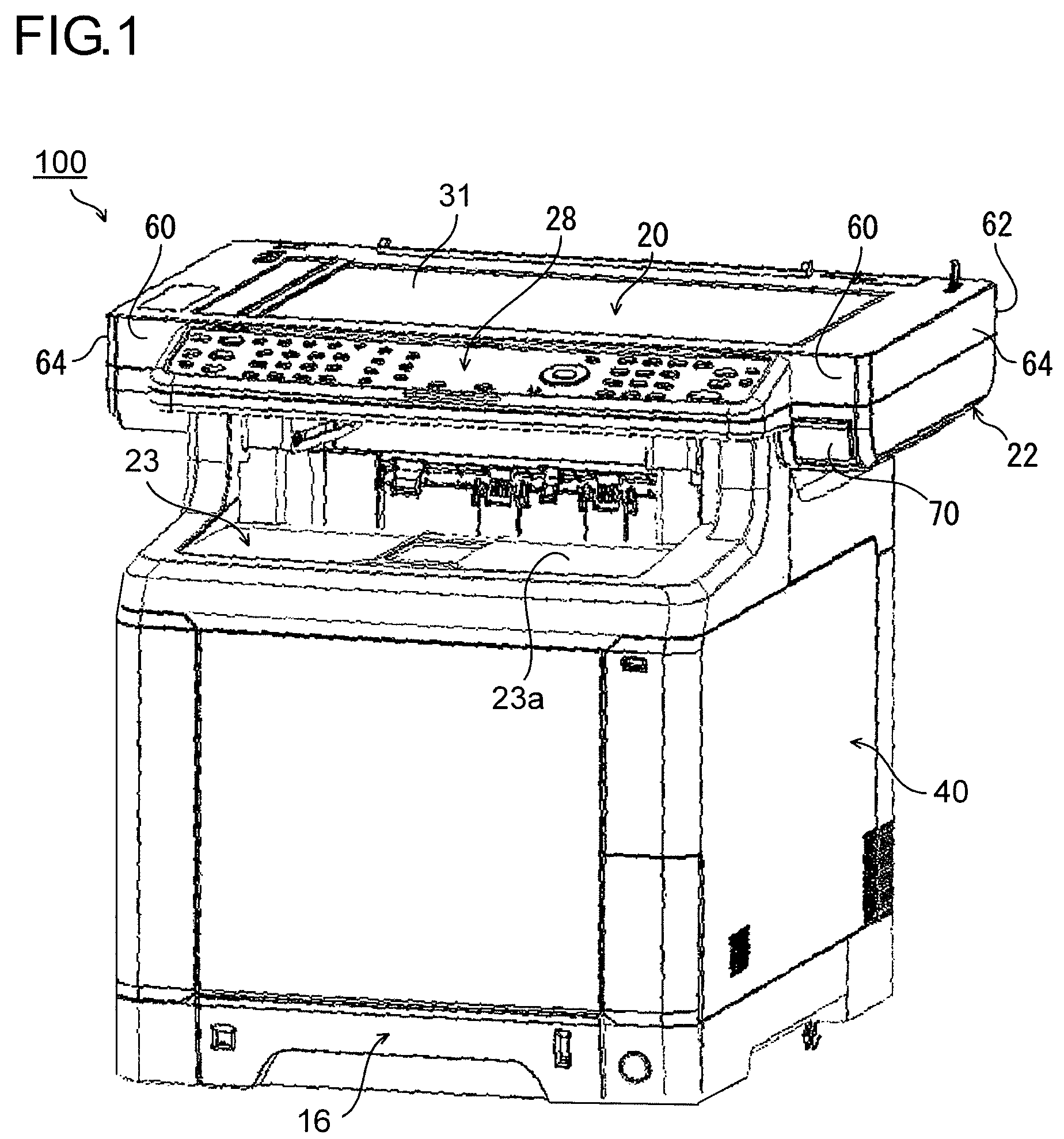
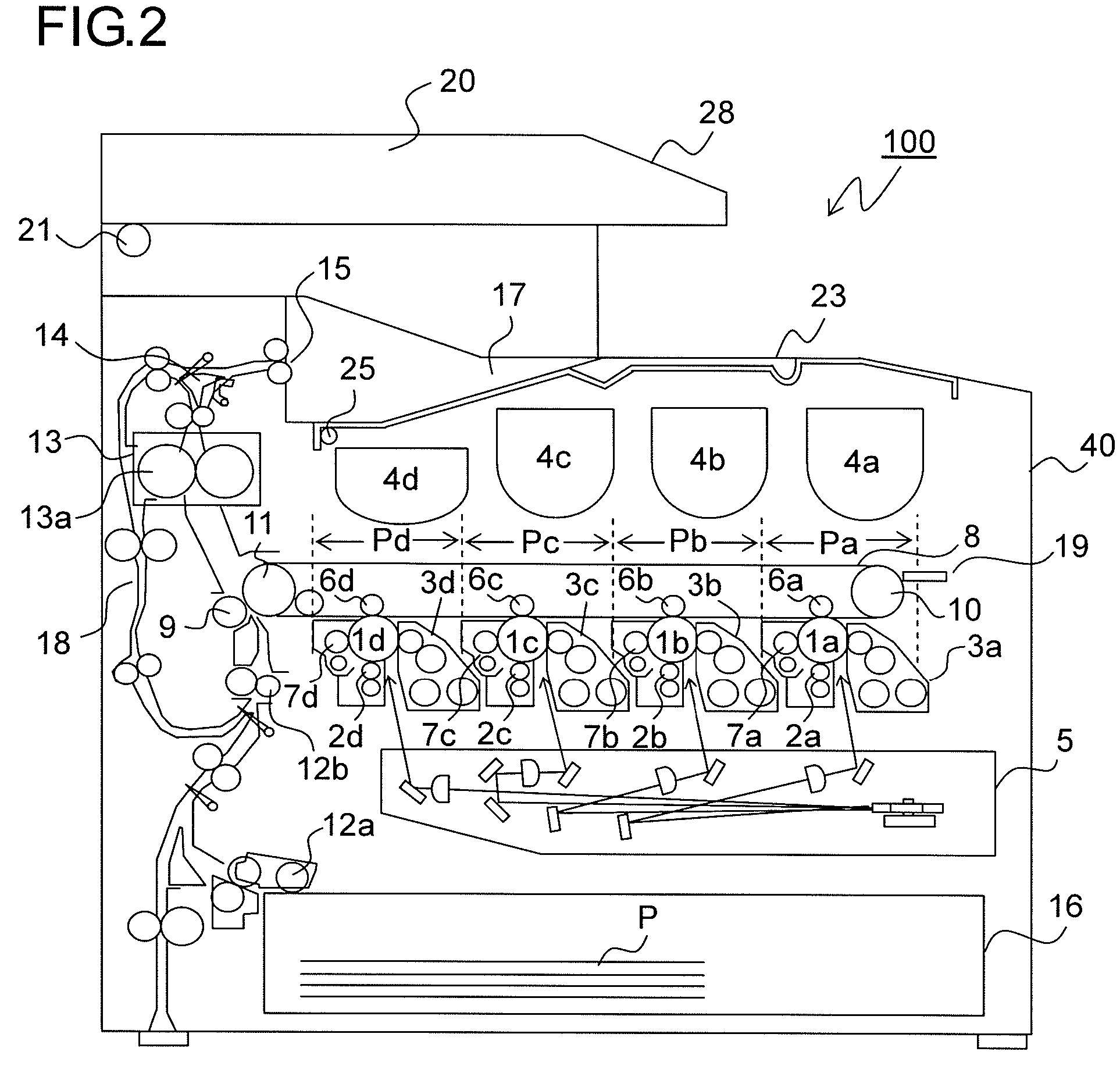
[0028]Hereinafter, embodiments of the present invention will be described with reference to the accompanying drawings. FIGS. 1 and 2 are external perspective view and schematic sectional view of an image forming apparatus according to the first embodiment of the invention, where a color digital compound machine of a tandem type, a so-called multiple function peripheral (hereinafter referred to as MFP) is shown. Shown in FIG. 1 are: a front surface of the MFP 100 facing a user; and a right side surface of the MFP 100. This MFP 100 is provided with an apparatus main body 40 of a box shape, above which paper is discharged.

[0029]Specifically, the top of an apparatus main body 40 is covered with an outer cover 23, and a top surface 23a of the outer cover 23 shown in FIG. 1 functions as a discharge tray 17 (see FIG. 2). Right, left, and rear sides of the apparatus main body 40 of this embodiment protrudes upward and rearward with respect to the top surface 23a in FIG. 1, and above the app...


PUM


Abstract

Am MFP (100) is provided with: a casing (22) which is turnably supported at a turning support point (25) to an apparatus main body (40) and which stores an image reading part (20) capable of optically reading a document; and an outer cover (23) which is turnably supported at a turning support point (21) to the apparatus main body (40) and which has a top surface (23a) opposing a bottom surface (66) of the casing (22) and a bottom surface (23b) covering image forming means, and is provided with a suspending mechanism that opens and closes the outer cover (23) in conjunction with opening and closing operation of the casing (22), and the turning support point (21) of the outer cover (23) is arranged with a distance from the turning support point (25) of the casing (22) toward a turning end of the casing (22).

Description

[0001]This application is based on Japanese Patent Application No. 2009-278531 filed on Dec. 8, 2009 and Japanese Patent Application No. 2009-297776 filed on Dec. 28, 2009, the contents of which are hereby incorporated by reference.BACKGROUND OF THE INVENTION[0002]1. Technical Field of the Invention[0003]The present invention relates to an image forming apparatus and more specifically to an improvement in maintainability of a copier provided with an image reading part above an image forming part.[0004]2. Description of Related Arts[0005]Conventionally known is a xerographic image forming apparatus that attaches a toner to an electrostatic latent image formed on an image carrier to form a visible image (toner image) and then transfers it onto a recording medium. Put into practice in such an image forming apparatus is a method of improving maintenability by using a cartridge-type toner container that refills a developing device with a toner or using a developing cartridge that integra...

Claims


Application Information

Patent Timeline
Patent Type & Authority Patents(United States)
IPC IPC(8): G06F3/12
CPCH04N1/00543H04N1/00554G03G21/1633G03G2215/0132G03G2221/169H04N2201/0094
Inventor NAGASGIMA, TERUHIKOMATSUNO, AKINORI
Owner KYOCERA DOCUMENT SOLUTIONS INC
Why Eureka
Try Eureka