Spike device for an anti-slid shoe

a technology of a spike device and a shoe, which is applied in the direction of lighting and heating equipment, applications, washing apparatus, etc., can solve the problems of excessive wear of spikes and certain surfaces, spikes are in constant contact with ground surfaces, and conventional spiked shoes suffer from drawbacks, so as to prevent relative movement

Active Publication Date: 2013-12-17
GRIP FORCE TECH
View PDF24 Cites 5 Cited by
  • Summary
  • Abstract
  • Description
  • Claims
  • Application Information

AI Technical Summary

Benefits of technology

[0011]An object of this invention is to provide an anti-slid shoe with retractable spikes and that is less complex and more reliable than what is previously known.
[0015]An advantage of such a design is that the use of conventional coil springs for the automatic retraction of the spikes can be avoided. Incorporating such coil springs into the shoe makes, the production complicated. Moreover, the function of coil springs is likely to be inhibited due to dust, dirt and corrosion.
[0016]Another advantage is that a proper sealing around the spike is much easier to achieve since the spike is fixed to the opening and thus moves together with the moving inner portion of the diaphragm means. In conventional spike devices the spike extends out from and retracts into a circular channel. In such a design it is virtually impossible to prevent dirt, salt etc. from entering the channel.
[0017]A further advantage is that the spike is held steady when protruding from the sole, i.e. the risk that the spike should be bent and / or come loose during use of the shoe is low.
[0018]In an advantageous embodiment of the invention the elastic diaphragm means has a cup-shaped portion that is adapted to generate a spring force when subjected to an axial depression force, which spring force is capable of restoring the cup-shape when the depression force is removed. An advantage of using such a dome-shaped diaphragm means, compared to e.g. a flat piece of elastic material, is that the distance the spike moves when switching between its retracted and extended positions, i.e. the length of the spike stroke, can be made longer without exposing the diaphragm means to significant stress. An increased spike stroke length makes it easier to accomplish both a sufficient retraction and a sufficient extension of the spike. Further, reducing the stress leads to a more durable product. A dome-shaped diaphragm means has an additional advantage in that it efficiently removes dirt that may accumulate around the spike. Preferably, the inner portion forms a bottom part of the cup-shaped portion such that the spike protrudes from the bottom part in an axial direction inside the cup-shaped portion.
[0029]In an advantageous embodiment of the inventive shoe it comprises an adjustable locking plate and spacing means adapted to allow prevention of the relative movement between the lower sole member and the upper sole member.

Problems solved by technology

Conventional spiked shoes suffer from the drawback that the spikes are in constant contact with ground surface during wear, also in situations where spikes are not necessary, such as on hard surfaces, or where spikes are unsuitable, such as on most indoor floors.
This causes excessive wear on the spikes and certain surfaces or makes a frequent switching of shoes necessary.
General problems associated with the known shoes with retractable spikes are a complex structure, a low structural strength and / or functioning problems when exposed to dirt.

Method used


Image

  • Spike device for an anti-slid shoe
  • Spike device for an anti-slid shoe
  • Spike device for an anti-slid shoe

Examples


Embodiment Construction

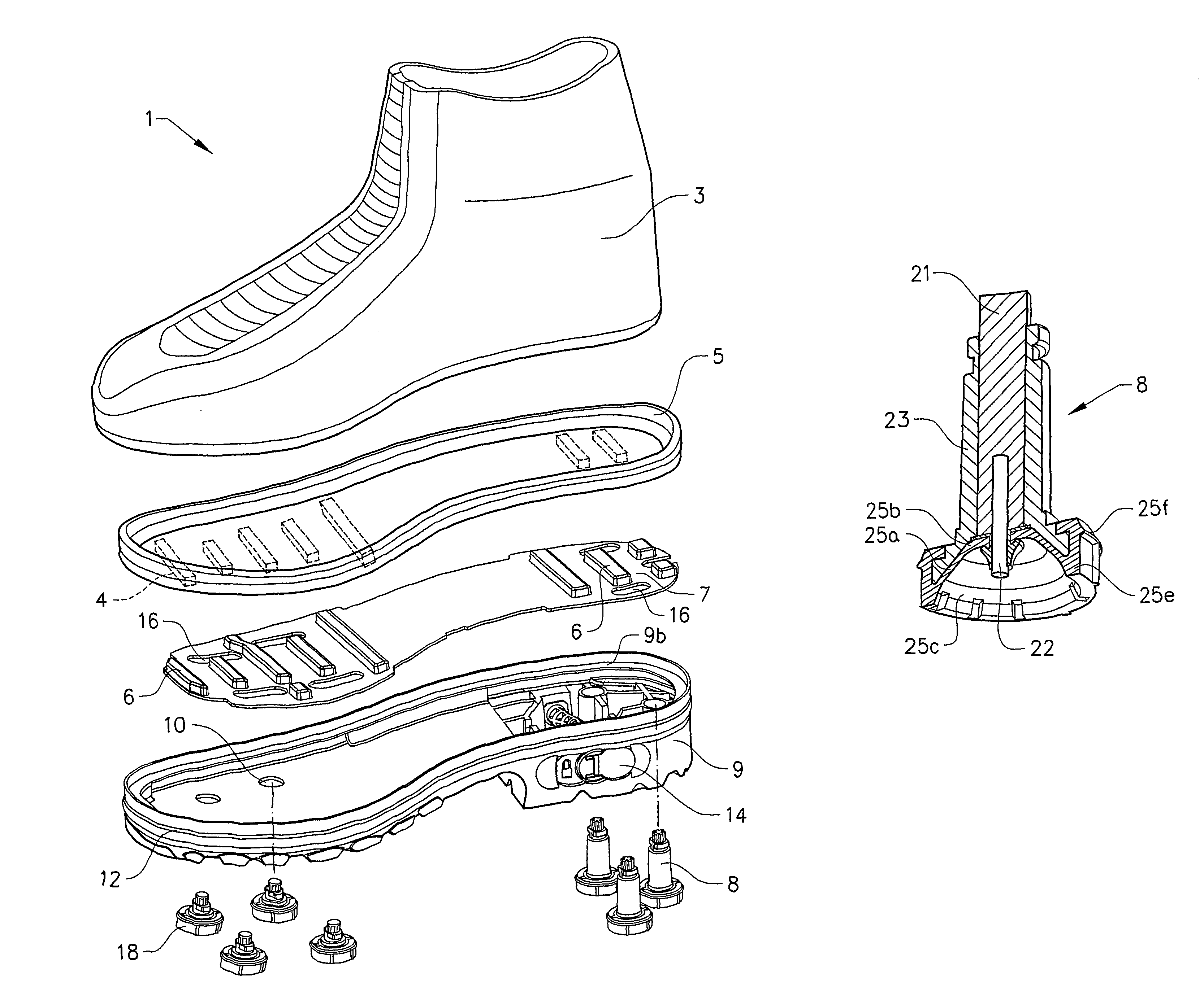
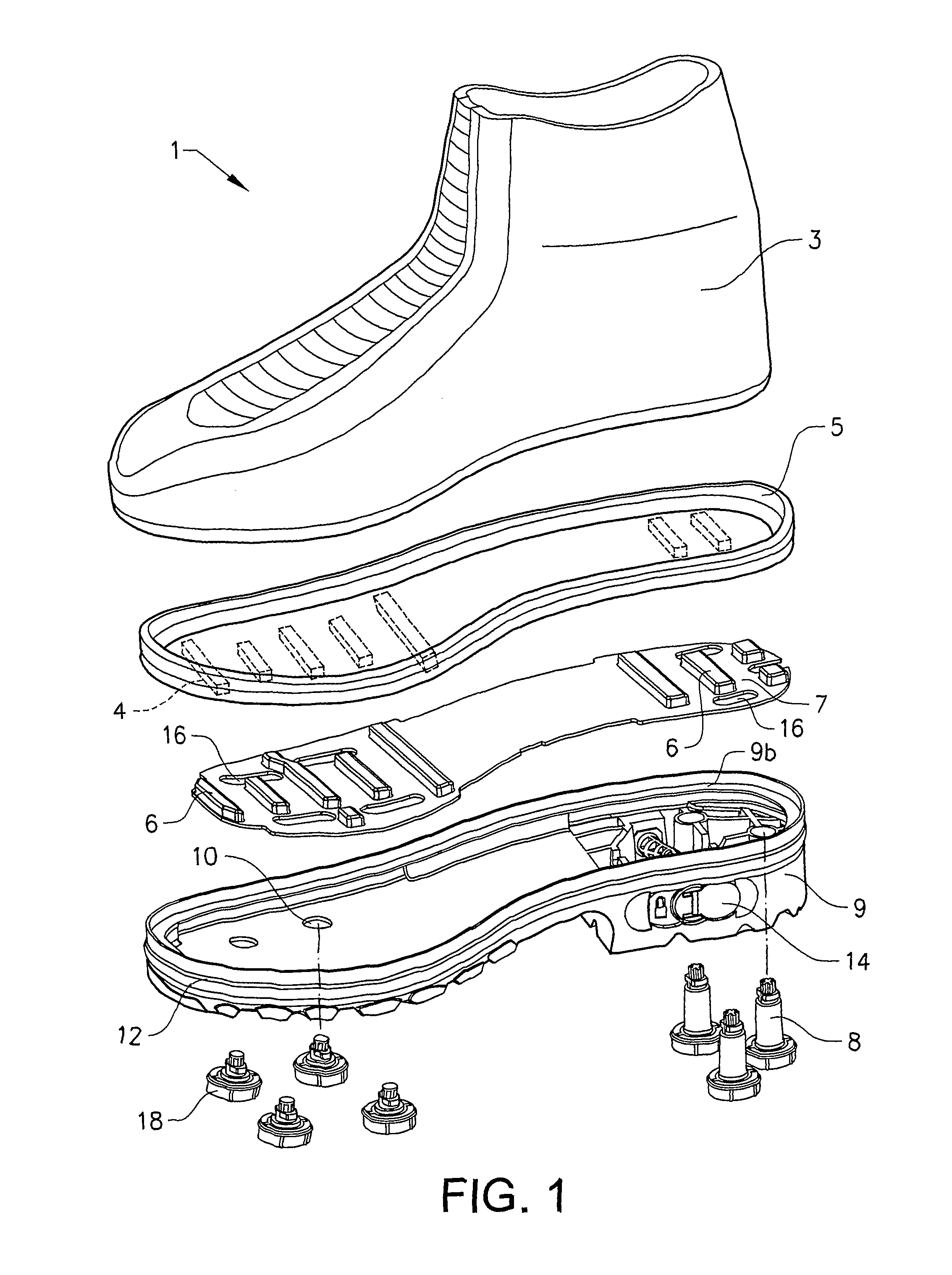
[0043]FIG. 1 shows, in an exploded view, a preferred embodiment of an anti-slid shoe 1 according to the invention. The shoe 1 comprises an upper part 3, an upper sole member 5, a locking plate 7, a lower sole member 9 and a plurality of rear and front spike devices 8, 18. The lower sole member 9 is provided with a corresponding plurality of openings 10 for receiving the spike devices 8, 18. The spike devices 8, 18 are fastened to the lower sole member 9 when positioned in the corresponding openings 10.

[0044]The shoe 1 is arranged such as to allow variation of the distance between the upper and the lower sole members 5, 9 (except at some areas in the very front and in the arch part of the shoe where this variation is not important for the function of the spikes). A flexible sole connecting means 12 connects the upper and lower sole members 5, 9. The upper sole member 5 is, on its underside, provided with first spacing means 4 extending towards the locking plate 7. The locking plate 7...


PUM


Abstract

Various embodiments provide a spike device for a sole of an anti-slid shoe. The device comprises at least a spike and a resilient member comprising an elastic diaphragm hving an inner portion and an outer portion. A spike unit comprising the spike is arranged in an opening in the inner portion of the elastic diaphragm such that the spike protrudes in an axial direction from the elastic diaphragm. The spike unit is movable in an axial direction and fixed in relation to the opening so as to allow the spike unit to move together with the inner portion of the elastic diaphragm. The spike device further comprises a guiding and supporting means for guiding the axial movement of the spike unit when the inner poriton moves in relation to the outer portion. A shoe comprising the spike device is also provided, having respective lower and upper sole members.

Description

CROSS REFERENCE TO RELATED APPLICATIONS[0001]This application is a national stage application, filed under 35 U.S.C. §371, of International Application No. PCT / SE2008 / 000187, filed Mar. 7, 2008, which is hereby incorporated by reference in its entirety.BACKGROUND OF THE INVENTION[0002]1. Field of Invention[0003]This invention relates to a spike device for a sole of an anti-slid shoe. The invention also relates to a shoe comprising such a spike device.[0004]2. Description of Related Art[0005]Shoes equipped with spikes are used for getting a good grip on slippery surfaces. Typically, spiked shoes are useful for people walking on streets or pavements covered with snow and ice and for golfers. Conventional spiked shoes suffer from the drawback that the spikes are in constant contact with ground surface during wear, also in situations where spikes are not necessary, such as on hard surfaces, or where spikes are unsuitable, such as on most indoor floors. This causes excessive wear on the ...

Claims


Application Information

Patent Timeline
Patent Type & Authority Patents(United States)
IPC IPC(8): A43C15/02A43C15/14
CPCA43C15/14A43C15/168
Inventor ANG.MARK, MIKAEL
Owner GRIP FORCE TECH
Why Eureka
Try Eureka