
Impact igniting incendiary device for projectiles

Active Publication Date: 2013-12-17
GOVERNMENT OF THE UNITED STATES AS REPRESENTED BY THE SEC OF THE AIR FORCE
View PDF18 Cites 5 Cited by
  • Summary
  • Abstract
  • Description
  • Claims
  • Application Information

AI Technical Summary

Benefits of technology

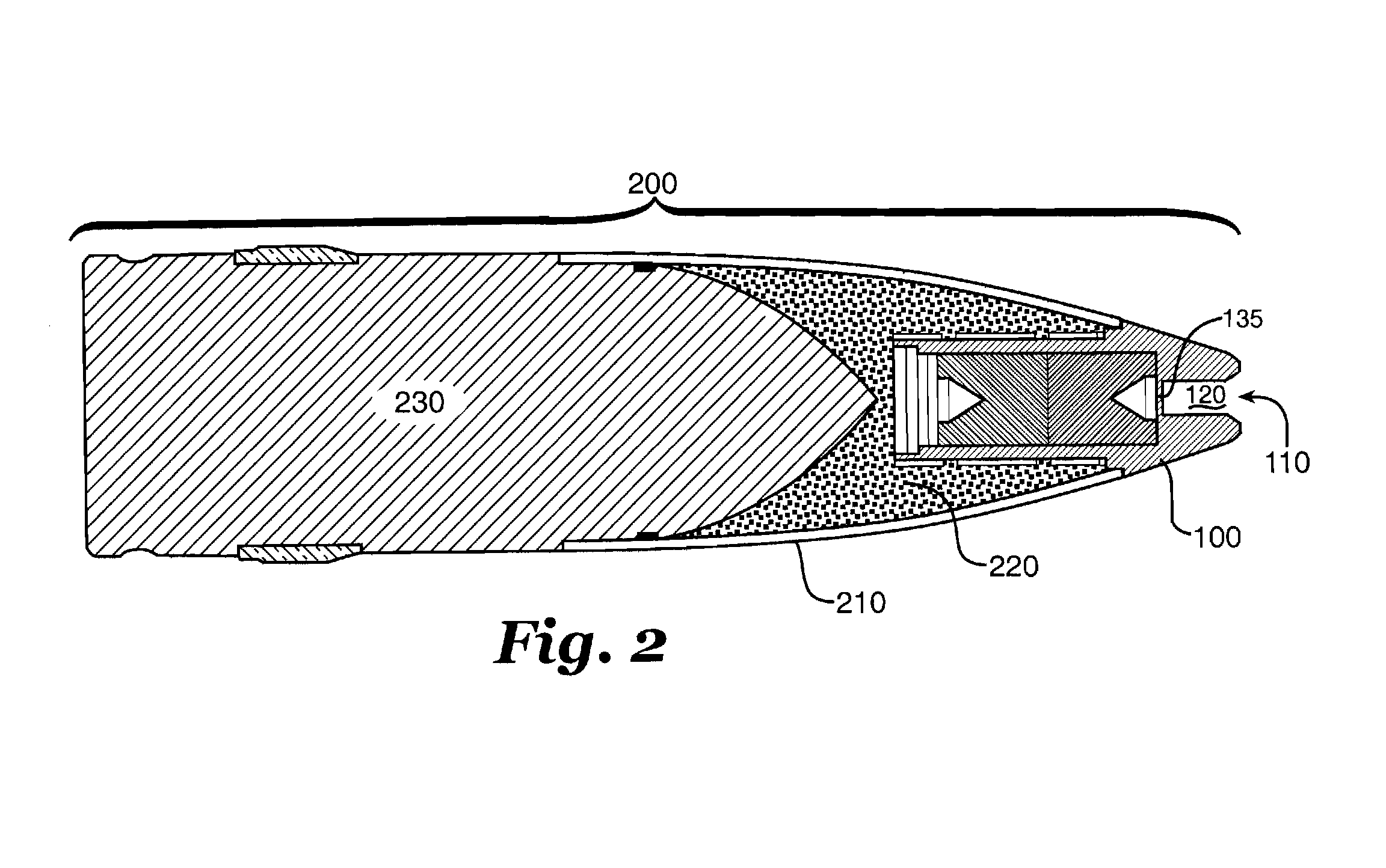
The present invention provides a new spotting charge capsule assembly for non-explosive containing projectiles, such as armor-piercing rounds or practice rounds, that converts them into spotting shells. The new capsule is insertable into the front of a projectile and provides both visual and auditory signatures on impact with both soft and hard surfaces, giving a shooter an absolute reference point of impact. The capsule can be used with existing stockpiles of conventional training ammunition and for newly manufactured ammunition. Additionally, the invention provides an auditory and visual signature when a hard target impact occurs without requiring a separate percussion primer. The spotting charge capsule has a front and a length with an opening, a bore, a cavity, and an incendiary mixture inside the cavity. The capsule may also include a void in the incendiary mixture near the bore end and a thin wall between the bore end and the cavity.

Problems solved by technology

Such high-explosive incendiary shells are in both short supply and expensive, severely limiting their use for training.
There is a large supply of surplus World War II 40 mm armor-piercing rounds that are used for training, but because they don't contain any explosive, it is difficult to visually determine ground strikes.
Without an impact signature, aircrews and ground crews cannot assess shot placement and correct the fire control system for errors.
A careful search of the prior art reveals that all these prior art spotting charges use complex mechanisms to trigger or ignite the spotting charge or other explosive or incendiary material used for creating a visual or audible, or both, effect.
While the Betts spotting charge is a clear improvement in simplicity over the other prior art, it is limited to use with hard targets.

Method used


Image

  • Impact igniting incendiary device for projectiles
  • Impact igniting incendiary device for projectiles
  • Impact igniting incendiary device for projectiles

Examples


Embodiment Construction

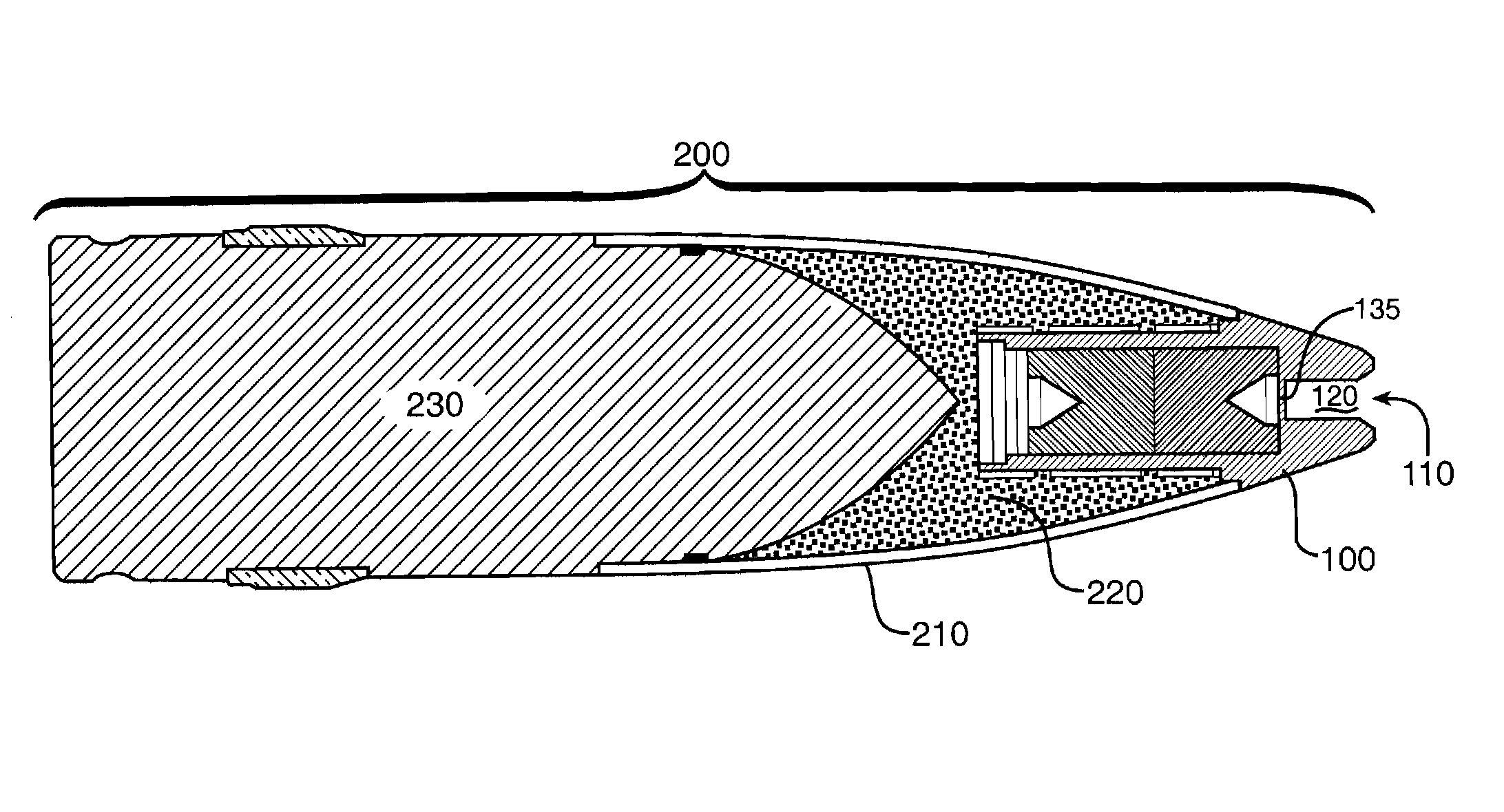
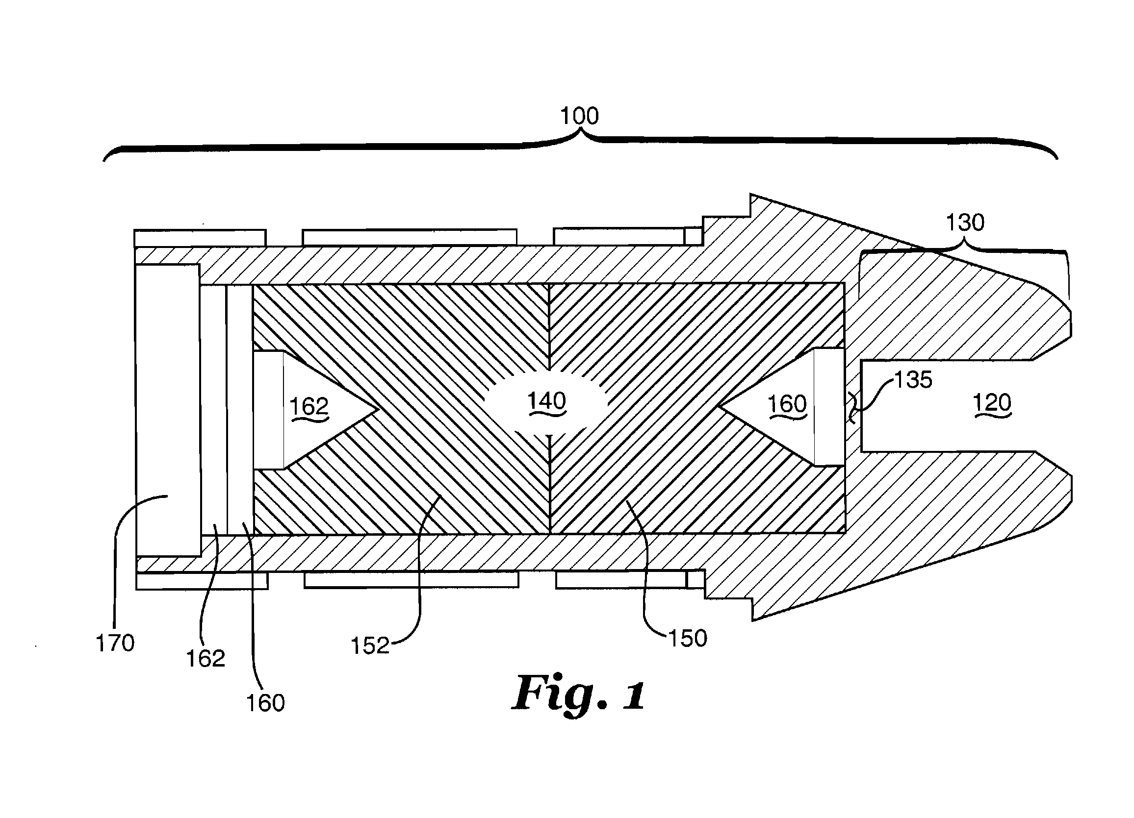
[0023]FIG. 1 is a cross-sectional view of an example embodiment of a spotting charge capsule 100 according to the teachings of the present invention. An opening 110 connects to a narrower bore 120 to create a venturi, or venturi-like, tube 130. Tube 130 is referred to here as a venturi tube because, as will be shown, creating a venturi effect, that is, causing whatever flows through the tube to increase its velocity, is desirable, and is most descriptive of the operation of the invention, but is not absolutely critical to its successful operation.

[0024]Venturi tube 130 extends to near a cavity 140 formed inside capsule 100, leaving a thin wall section135 separating venturi tube 130 from cavity 140. An incendiary mixture, in this example embodiment comprising a pair of pressed incendiary pellets 150 and 152, mostly fills cavity 140 and includes a pair of conical voids 160 and 162.

[0025]The back of cavity 140 is sealed, as shown here, with a pair of felt disks 160 and 162 and an alumi...


PUM


Abstract

An improved apparatus and method for fitting a normally non-explosive containing projectile with a spotting charge. A spotting charge capsule is inserted into an opening in the front of a projectile. The opening may be made by removing part of the nose of the projectile and making a shaped opening for inserting the spotting charge capsule. The spotting charge capsule includes an opening at its front and a bore behind the opening leading to a cavity for holding an explosive mixture, usually one or more pressed incendiary pellets. The opening and bore together form a venturi, or venturi-like, tube. The tube ends short of the cavity leaving only a thin wall between the bore and the explosive. On impact on soft media, such as dirt, sand or mud, the soft media will enter the tube and shear the thin wall, creating a high speed flier plate that ignites the explosive mixture.

Description

RIGHTS OF THE GOVERNMENT[0001]The invention described herein may be manufactured and used by or for the Government of the United States for all governmental purposes without the payment of any royalty.BACKGROUND OF THE INVENTION[0002]The present invention relates generally to cannon ammunition and other projectiles, and more specifically to an insert assembly that adds a spotting charge to normally non-explosive shells.[0003]Air Force AC-130 gunship weapons include a 40 mm Bofors cannon. For most military operations, the cannon fires a high explosive incendiary shell.[0004]Such high-explosive incendiary shells are in both short supply and expensive, severely limiting their use for training.[0005]There is a large supply of surplus World War II 40 mm armor-piercing rounds that are used for training, but because they don't contain any explosive, it is difficult to visually determine ground strikes. Without an impact signature, aircrews and ground crews cannot assess shot placement and ...

Claims


Application Information

Patent Timeline
IPC IPC(8): F42B12/40
CPCF42B12/40
Inventor MCCLENAHAN, CHARLES H.WALTER, WILLIAM B.RUMCHICK, CHAD G.COOKSEY, JR., MITCHEAL A.
Owner GOVERNMENT OF THE UNITED STATES AS REPRESENTED BY THE SEC OF THE AIR FORCE
Learn More