Sensor

a sensor and sensor technology, applied in the field of sensors, can solve problems such as room disfigurement, achieve the effects of reducing obstacle factor, preventing deterioration of detection ability in the detecting part, and being smaller and thinner

Inactive Publication Date: 2013-12-17
PANASONIC CORP
View PDF27 Cites 13 Cited by
  • Summary
  • Abstract
  • Description
  • Claims
  • Application Information

AI Technical Summary

Benefits of technology

[0023]According to the present invention, the sensor can be made smaller and thinner by providing the detecting part in the housing. The guide member constituting the flow path dividing the space including the detecting part and extending from the opening to the detecting part is provided, so that the fluid flown from the opening can be guided to the detecting part, thereby preventing deterioration of detection ability in the detecting part.
[0024]Further, the constituting member which has been obstacle to guiding the fluid from the opening to the detecting part can be used as a part of the guide member, thereby reducing obstacle factor for guiding the fluid in the guide path from the opening to the detecting part. The constituting member required for the sensor is used as the guide member, so that useless guide member is not required to be provided. When the bar is provided for securing the strength of the housing, the bar is connected to the end part of the guide member, thereby controlling by the guide member reduction of guide ability based on the change in the pressure distribution by the bar. In addition, when the bypass of fluid between the guide paths is provided, the fluid to be detected can be rapidly guided to the detecting part. Accordingly, much fluid to be detected rapidly flows in the detecting part to enhance the responsiveness on detection of the environmental value by the detecting part.
[0025]Still further, when the separating plate is provided in the housing, the second space having the sounding body and the fist space having the detecting part can be separated. Accordingly, the affect on the fluid to be flown in the detecting part based on the alarm operation of the sounding body can be reduced and the affect thereof on the measuring operation in the detecting part can be inhibited. In addition, the second space is formed by the separating plate so as to provide the sounding body, the air resistance in the second space can be prevented when the sounding body triggers alarm. When the second opening is provided so as to open the second space having the sounding body into the space outside of the housing, the air resistance in the second space can be further reduced, and as the result, the external sound volume of the alarm can be large.
[0026]Still further, when the shielding cover is provided in the housing including the detecting part, the space comprised of the detecting part and the guide part can be constituted as an independent space in the housing so that foreign matter can be prevented from entering in the guide part provided in the housing together with the detecting part. The shielding cover blocks the guide part from another space in the housing and an operator is prevented from getting in touch with the structure guiding the fluid to be detected into the detecting part. In addition, the space where the guide part is provided is constituted as an open space with the opening, thereby preventing air flow other than the fluid flow from the opening to the detecting part by the guide part. Further, an operator is prevented from contacting the guide member by means of the shielding cover during setting operation of the alarm or exchanging operation of battery.

Problems solved by technology

However, such a sensor having the projected detecting part 201 is provided in a room, it is not suitable for room design and it causes disfigurement of the room.

Method used


Image

  • Sensor
  • Sensor
  • Sensor

Examples


sixth embodiment

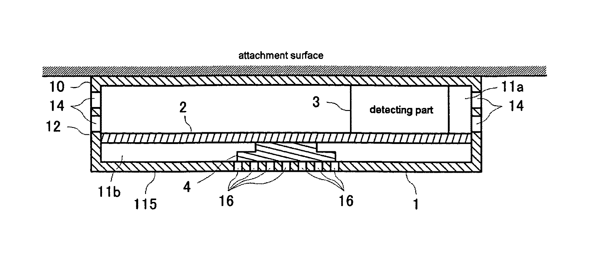
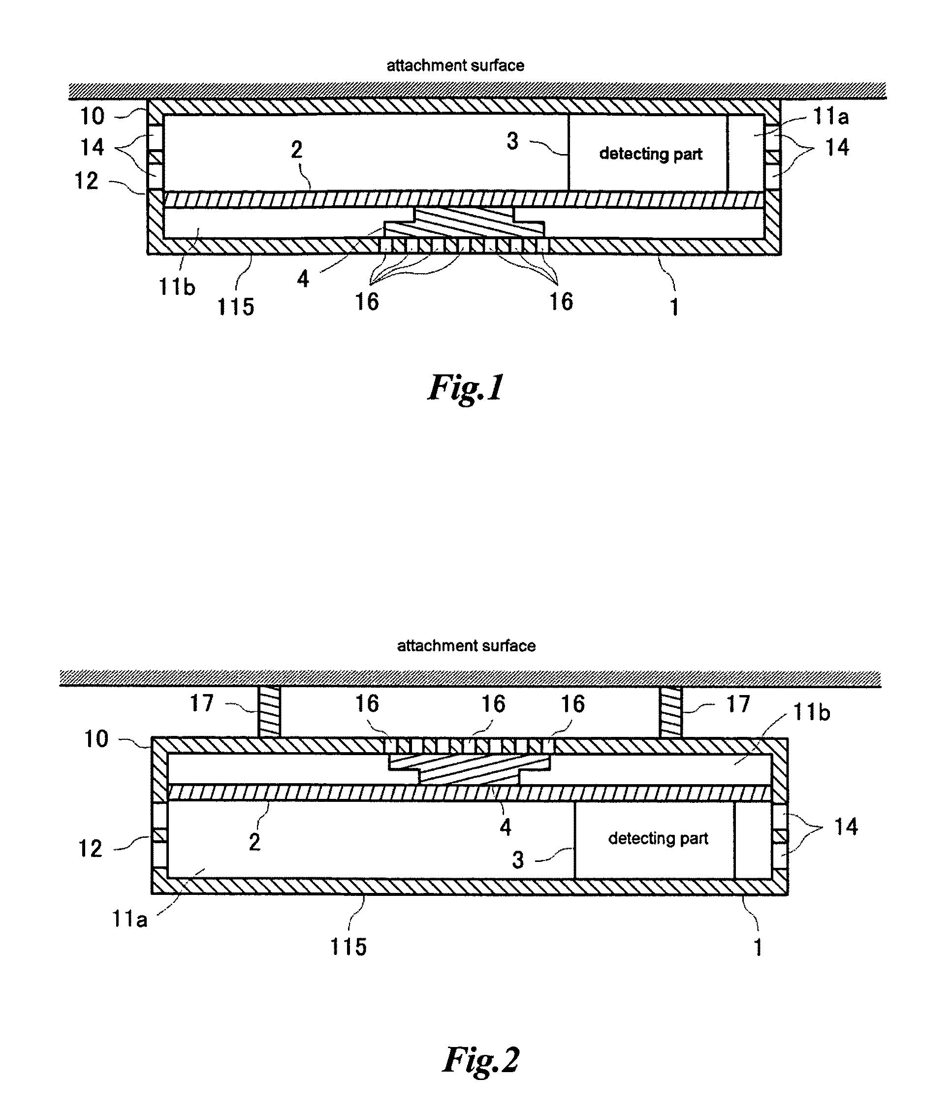
[0158]A sensor according to the sixth embodiment of the present invention is explained referring to the drawings. FIG. 11A is a diagrammatic plan view showing the internal structure of the sensor according to this embodiment and FIG. 11B is a diagrammatic sectional view along the line X-X direction in the plan view of FIG. 11A. The same members in this embodiment as those in the second embodiment are allotted with the same reference numerals and their explanation is omitted.

[0159]The sensor of this embodiment is designed such that a battery 6 which is a power source having a relatively large setting area in the apparatus, the detecting part 3, and the sounding body 4 are provided in a position which does not interfere each other. And the sensor has a circuit board 20 mounting the detecting part 3 (shown with broken line in FIG. 11A) on the surface thereof on the first space 11a side and an operation button 60 which is electrically connected to the circuit board 20 for receiving spec...

seventh embodiment

[0168]A sensor according to the seventh embodiment of the present invention is explained referring to the drawings. FIG. 13 is a diagrammatic plan view showing the structure in the first space of the sensor according to this embodiment. In FIG. 13 the same members as those in FIG. 11A and FIG. 11B are allotted with the same reference numerals and their explanation is omitted.

[0169]The sensor of this embodiment has a guide wall 51 for guiding the fluid flown from the opening 14 of the side wall 12 into the detecting part 3 in the first space 11a having the detecting part 3 as shown in FIG. 13. Other structures are same as those in the sixth embodiment, their explanation is to be referred to that of the sixth embodiment and is omitted here.

[0170]The guide wall 51 is provided with a space along the outer circumference of the detecting part 3 and its longitudinal direction extends to the opening 14 of the side wall 12 from the outer circumference of the detecting part 3. A plurality of ...

eighth embodiment

[0174]A sensor according to the eighth embodiment of the present invention is explained referring to the drawings. FIG. 14 is a diagrammatic sectional view of the space including the detecting part in the housing, showing the structure of the sensor of this embodiment.

[0175]The sensor of this embodiment has the detecting part 3 for measuring the environmental value when the fluid in the circumference environment (outer environment) out of the housing 1 flows in and the detecting part 3 is provided at the center of the housing 1 as shown in FIG. 14. The side wall 12 surrounding the periphery of the housing 1 has the opening 14 as mentioned later referring to the structure shown in the sectional views of FIG. 16 and FIG. 17 and the fluid flowing in the outer environment at the peripheral side of the side wall 12 flows in the housing 1 from the opening 14.

[0176]When the detecting part 3 is provided at the center of the housing 1 relative to the face parallel to the attachment surface o...


PUM


Abstract

A sensor having a detecting part for detecting an environmental value representing change in physical amount of circumference environment by a fluid flowing into externally and a controlling part for discriminating abnormality in circumference environment based on the environmental value detected by the detecting part. A separating plate is provided inside a housing so as to separate two spaces in the height direction. A detection unit is provided in one space and a sounding body is provided in the other space. Apertures are provided in a side wall, thereby opening one space to the outside environment and letting the fluid to be measured flow into the space. Then, a flow path is formed inside the space in the housing, from the side wall forming the housing toward the detection unit, thereby proactively channeling the fluid to the detection unit.

Description

TECHNICAL FIELD[0001]The present invention relates to a sensor measuring an environmental value representing environmental change from fluid flowing into a detecting part, and more specifically to a sensor having a detecting part in a housing.BACKGROUND ART[0002]A fire alarm informing a fire generally includes a heat detecting type fire alarm having a heat detecting element for detecting room temperature (refer to the Patent Citation 1), a smoke detecting type fire alarm having a smoke detector (refer to the Patent Citation 2), and a fire alarm having both types (refer to the Patent Citation 3 and the Patent Citation 4). The heat detecting type fire alarm determines fire generation when the temperature detected by the heat detecting element becomes high and announces an alarm as disclosed in the Patent Citation 1. On the other hand, the smoke detecting type fire alarm determines fire generation when the smoke amount detected by the smoke detector becomes large and announces an alarm...

Claims


Application Information

Patent Timeline
Patent Type & Authority Patents(United States)
IPC IPC(8): G08B21/00
CPCG08B17/10G08B17/113
Inventor SHIMADA, YOSHITAKEKOMATSU, MIKIOSAKAMOTO, KOJIOKUNO, HIROHISAHONDA, AKIKOYAMATO, KOJI
Owner PANASONIC CORP
Why Eureka
Try Eureka