
Magnetic etch-stop layer for magnetoresistive read heads

a technology of etchstop layer and read head, which is applied in the field of magnetic etchstop layer for magnetoresistive read head, can solve the problems of ineffective formation of skirts, reduced shield-to-shield spacing, and unsatisfactory formation of skirts, etc., and achieves soft magnetic properties, reduce shield-to-shield spacing, and reduce tw and junction angle sigmas

Active Publication Date: 2013-12-17
WESTERN DIGITAL TECH INC
View PDF29 Cites 163 Cited by
  • Summary
  • Abstract
  • Description
  • Claims
  • Application Information

AI Technical Summary

Benefits of technology

This patent introduces a new layer called a magnetic etch-stop layer, which has unique properties that make it useful in the manufacturing of semiconductors. This layer can help to reduce the space between shields, improve process control, and act as an etch-stop layer for specific processes. Overall, the use of this layer can lead to improved performance and reliability of semiconductor devices.

Problems solved by technology

However, the shield-to-shield spacing is reduced, the current AFM seed layer used in MgO TMR sensors is changed to CoFeB / NiFe magnetic seed layer, which is not effective as RIE etch-stop layer when using CH3OH etchant gas, for example.
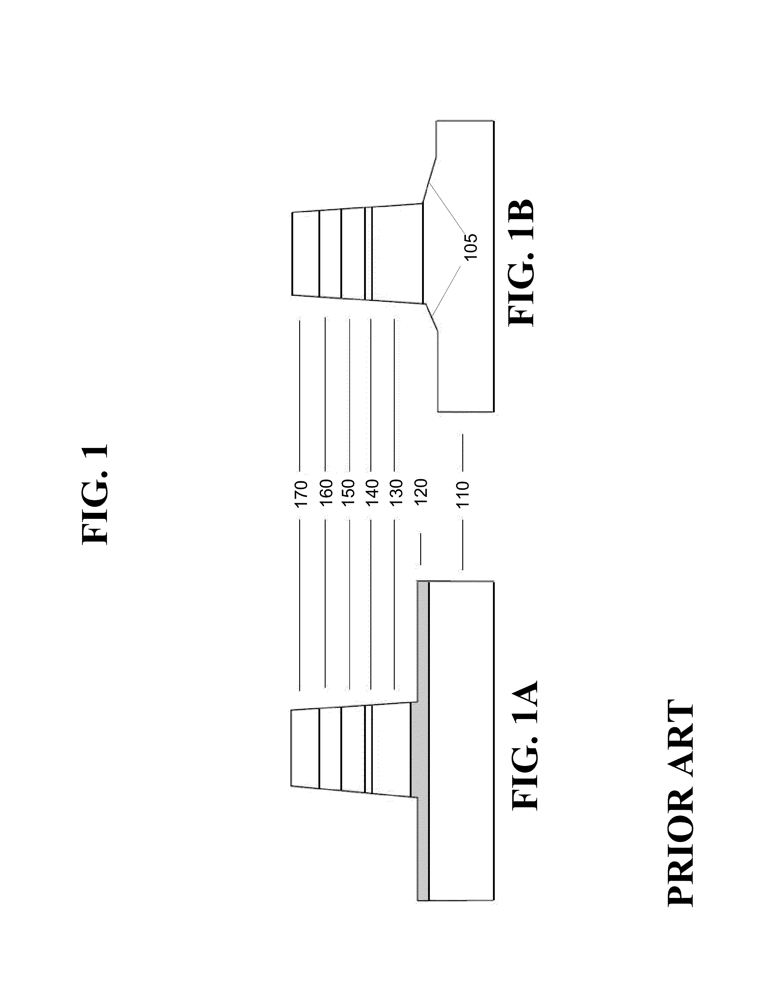
The formation of the skirts 105 is not desirable, as they hamper a good alignment between the free layer of the sensor and the hard bias used for stabilization.

Method used


Image

  • Magnetic etch-stop layer for magnetoresistive read heads
  • Magnetic etch-stop layer for magnetoresistive read heads
  • Magnetic etch-stop layer for magnetoresistive read heads

Examples


Embodiment Construction

[0020]In the following detailed description, numerous specific details are set forth to provide a full understanding of the present invention. It will be apparent, however, to one ordinarily skilled in the art that the present invention may be practiced without some of these specific details. In other instances, well-known structures and techniques have not been shown in detail to avoid unnecessarily obscuring the present invention.

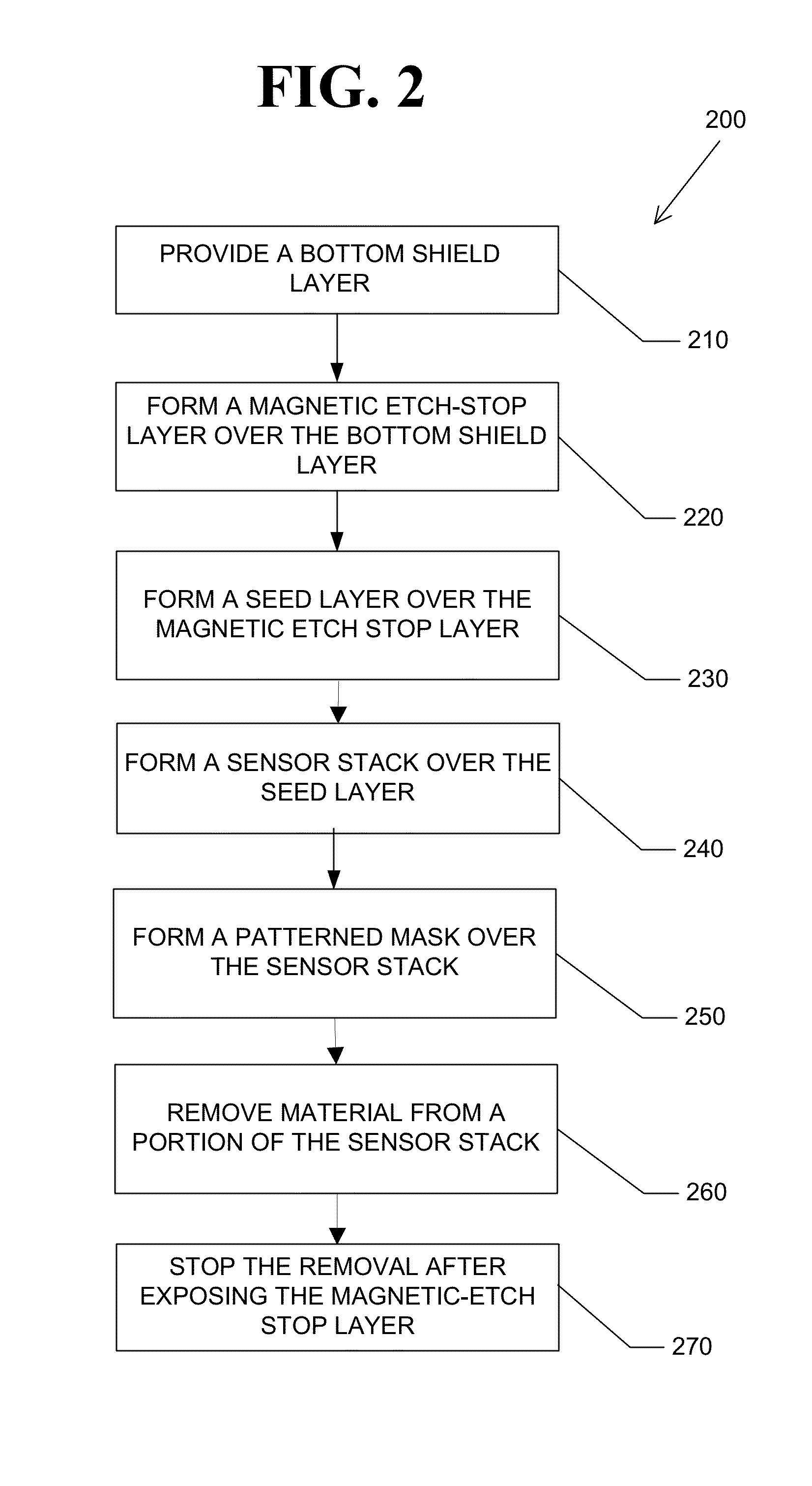
[0021]FIG. 2 is a flowchart illustrating an exemplary process 200 for producing magnetoresistive sensors (e.g., TMR or GMR sensors) using a magnetic etch-stop layer according to one aspect of the subject disclosure. The process 200 will be described with respect to exemplary pre-etch and post-etch TMR sensor structures 300A, 300B before and after RIE etching process, respectively, as shown in FIGS. 3A and 3B. The TMR sensor structures 300A and 300B comprise a bottom shield layer 310, a magnetic etch-stop layer 320 disposed over the bottom shield layer 310...


PUM


Abstract

A method of producing a magnetoresistive read head and a tunneling magnetoresistive read head produced thereby are disclosed. A shield layer is provided. A magnetic etch-stop layer is formed over the shield layer, where the magnetic etch-stop layer comprises a nonmagnetic metal and a soft magnetic material with overall property still being magnetically soft. A sensor stack is formed over the magnetic etch-stop layer. A patterned mask layer is formed over the sensor stack. Material from a portion of the sensor stack not covered by the patterned mask is removed.

Description

FIELD OF THE INVENTION[0001]The present invention generally relates to magnetoresistive read heads and, in particular, relates to magnetic etch-stop layer for magnetoresistive read heads.BACKGROUND OF THE INVENTION[0002]Magnetoresistive sensors such as tunnel magnetoresistance (TMR) sensors and giant magnetoresistance (GMR) sensors are frequently employed as sensing elements in the magnetic read heads of hard disk drives. As the areal density of hard disks approaches 1 Tb / in2, the size of read head shrinks in all three dimensions: track width (TW), shield-to-shield spacing, and stripe height. In current fabrication processes for magnetic read heads, an ion-beam-etch (IBE) process is used to define the track width. In general, fabrication of a contiguous junction (CJ) involves etching out the CPP sensor (TMR or GMR) by the IBE process to designed TW and junction angle. Subsequently, a thin insulator and permanent magnetic film are deposited along the TW direction to stabilize the sen...

Claims


Application Information

Patent Timeline
IPC IPC(8): G11B5/33
CPCG11B5/3163G11B5/3903G11B5/11G11B5/3909G11B5/3912G11B5/3929
Inventor PAKALA, MAHENDRAXIAO, RONGFUPARK, CHANDO
Owner WESTERN DIGITAL TECH INC
Learn More