Inductive Position Sensor with Improved Magnetic Shield and Plunger Core Design

a plunger core and inductive position sensor technology, applied in the direction of converting sensor output, measuring devices, instruments, etc., can solve the problems of not enabling a foil design per se, only having a soft magnetic plunger core, and a very important cost issue, so as to reduce the cost, reduce the cost, cost efficient and reliable design

Inactive Publication Date: 2020-01-02
SEM AB
View PDF0 Cites 0 Cited by
  • Summary
  • Abstract
  • Description
  • Claims
  • Application Information

AI Technical Summary

Benefits of technology

[0016]The invention is related to a new design in an inductive position sensor enabling a further cost reduction of the sensor wherein preferably the magnetic shield as well as the movable magnetic plunger core are made from electrical steel, or soft iron sheet material shaped in a hollow circular form. The common inventive objec...

Problems solved by technology

One disadvantage is that the cost for only the soft magnetic plunger core typically amounts to over 10%, often about 15%, of the total costs of the sensor (including coil winding and housing).
The cost issue is a very important issue for these inductive position sensors as they are used in large numbers in different syste...

Method used


Image

  • Inductive Position Sensor with Improved Magnetic Shield and Plunger Core Design
  • Inductive Position Sensor with Improved Magnetic Shield and Plunger Core Design
  • Inductive Position Sensor with Improved Magnetic Shield and Plunger Core Design

Examples


Embodiment Construction

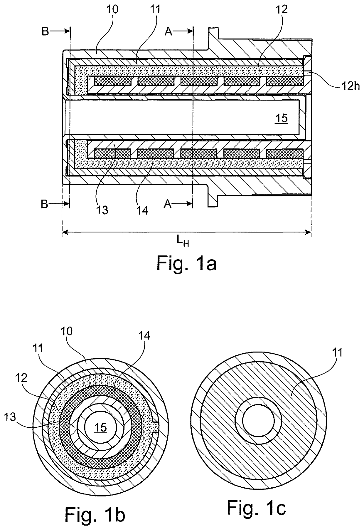
[0050]In FIG. 1a is shown a longitudinal cross section of the coil winding housing, without a movable plunger core. And in FIG. 1b is seen a cross section of the coil winding housing seen in the view A-A, and in FIG. 1c is seen a cross section of the magnetic shield seen in the view B-B.

[0051]The coil winding housing comprises an electrical winding 14 wound on an elongated electrical winding support 13 which may be equipped with winding chambers as seen in FIG. 1a. The turns of the coil winding are wound in an orthogonal plane crossing the longitudinal axis of the coil winding housing, and the length of the coil winding in the longitudinal direction is at least as long as the stroke of the motion to be detected (i.e. the stroke length of the plunger core later described). The total length of the coil winding housing is indicated with LH, i.e. slightly longer than the length of the coil winding.

[0052]The winding is encapsulated in some insulation material 12, which may be oil or resi...


PUM


Abstract

The invention relates to an inductive position sensor, comprising: a first part with a cylindrical coil winding (14) having a longitudinal direction, a second part with a soft magnetic plunger core (20). The invention also relates to the soft magnetic plunger core and a magnetic shield around said cylindrical coil winding for said inductive position sensor. According to the invention is the soft magnetic plunger core as well as the magnetic shield hollow, preferably with circular cross-section, and made from electrical steel or soft iron sheet material.

Description

BACKGROUND[0001]Different kinds of position sensors have been developed and one of the most common position sensors use an inductive position sensor, comprising a coil structure surrounding a plunger core movable in relation to the coil. The coil conventionally comprises an electrical winding wound on a bobbin.[0002]The coil when connected to an alternating voltage source produce a magnetic field and acts as a magnet, and the plunger core is made of soft magnetic material that change the inductance in the coil. The coil and associated parts forms one part of the position sensor, and the plunger core forms a second part that is movable versus the first part.[0003]Normally in a system where relative position between parts need to be controlled, the first part with the coil is stationary and the second part with the plunger core is attached with a movable part, but they may also be mounted in the opposite fashion.[0004]The position of the movable magnetic plunger core versus the coil c...

Claims


Application Information

Patent Timeline
IPC IPC(8): G01D5/20G01D5/22H01F3/14H01F29/10
CPCH01F3/14G01D5/2046G01D5/2291H01F29/10G01D5/2216G01D5/2013G01D5/2258G01D5/20
Inventor BENGTSSON, JÖRGEN
Owner SEM AB
Why Eureka
Try Eureka