Control flow analysis using deductive reaching definitions

a control flow and definition technology, applied in reverse engineering, instruments, computing, etc., can solve the problems of lack of precision, limiting the scope of the analysis, and limiting the application of the analysis

Inactive Publication Date: 2013-12-24
INT BUSINESS MASCH CORP +1
View PDF29 Cites 6 Cited by
  • Summary
  • Abstract
  • Description
  • Claims
  • Application Information

AI Technical Summary

Problems solved by technology

The conservative approach does not allow speculation of what value a variable may possess.
The result lacks precision.

Method used


Image

  • Control flow analysis using deductive reaching definitions
  • Control flow analysis using deductive reaching definitions
  • Control flow analysis using deductive reaching definitions

Examples


Embodiment Construction

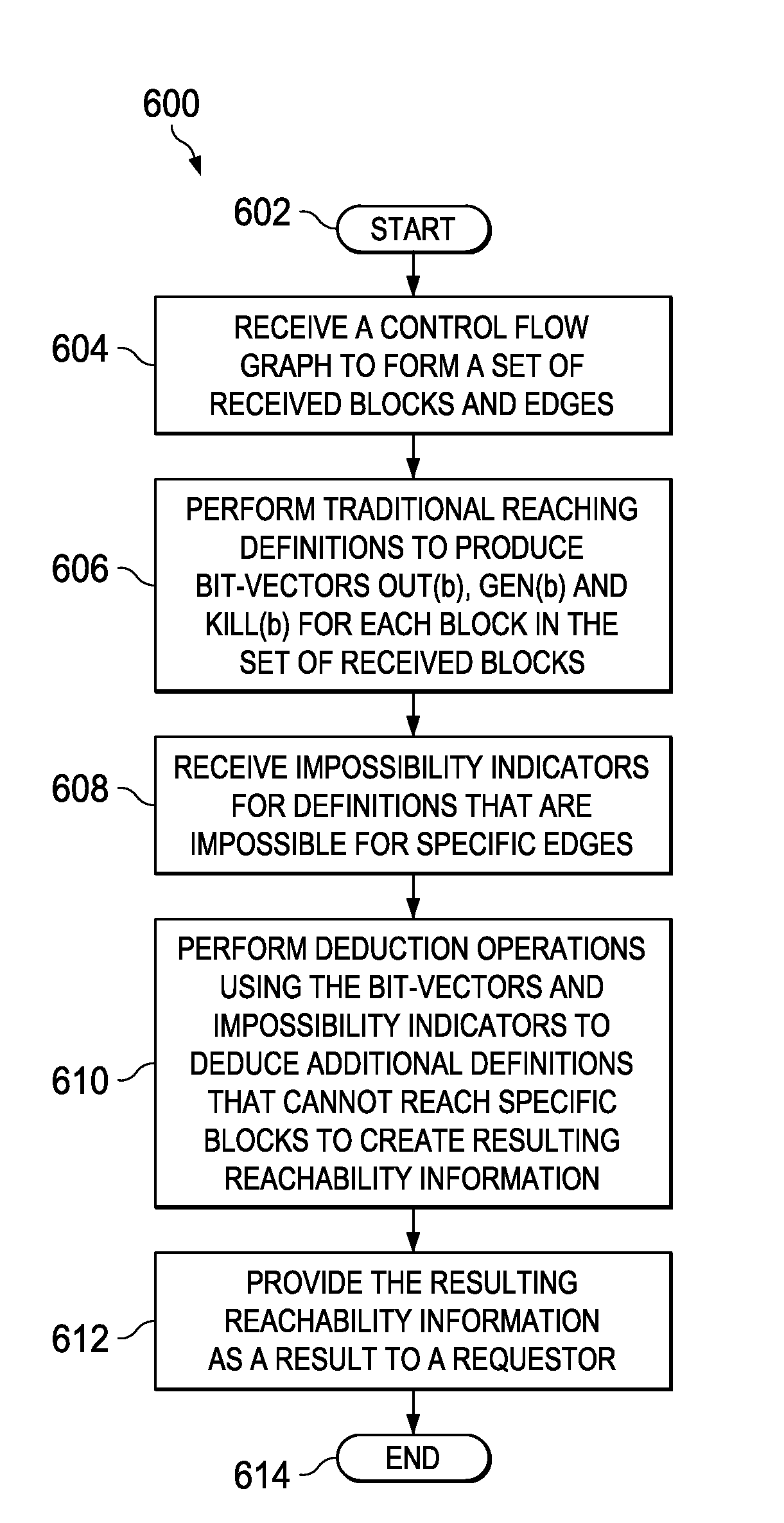
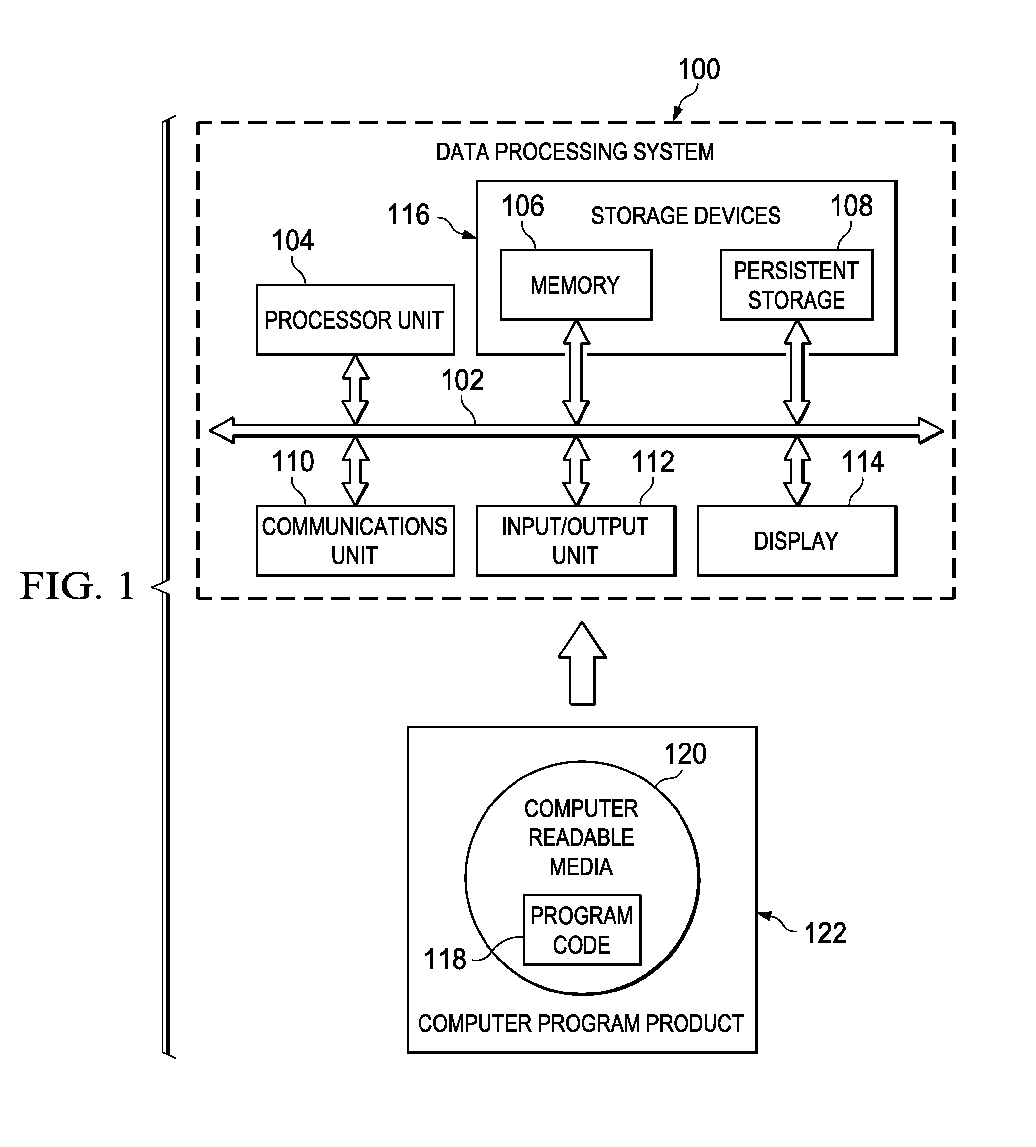
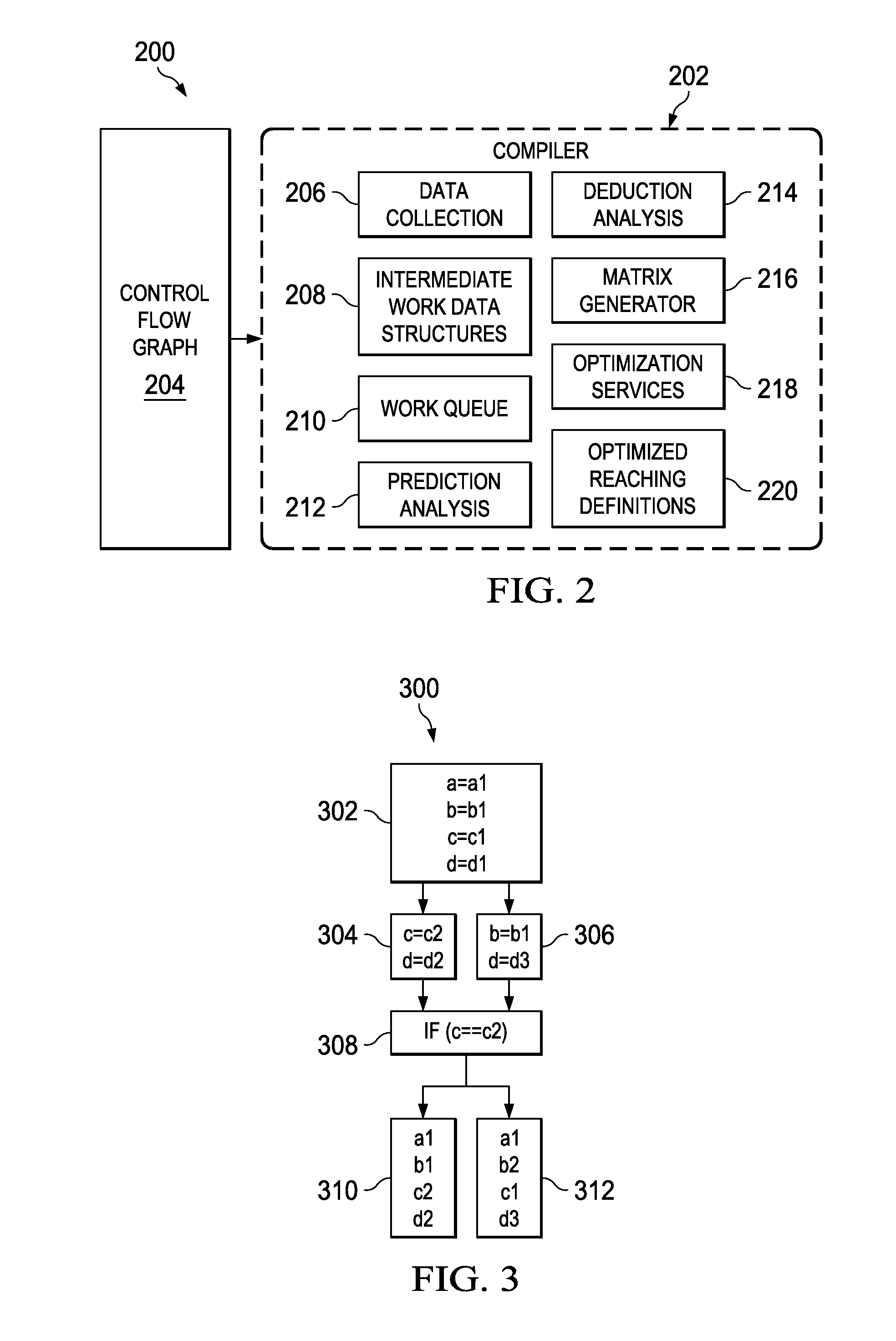
[0023]Although an illustrative implementation of one or more embodiments is provided below, the disclosed systems and / or methods may be implemented using any number of techniques. This disclosure should in no way be limited to the illustrative implementations, drawings, and techniques illustrated below, including the exemplary designs and implementations illustrated and described herein, but may be modified within the scope of the appended claims along with their full scope of equivalents.

[0024]As will be appreciated by one skilled in the art, the present disclosure may be embodied as a system, method or computer program product. Accordingly, the present disclosure may take the form of an entirely hardware embodiment, an entirely software embodiment (including firmware, resident software, micro-code, etc.) or an embodiment combining software and hardware aspects that may all generally be referred to herein as a “circuit,”“module,” or “system.” Furthermore, the present invention may ...


PUM


Abstract

A computer-implemented process for deductive reaching definition analysis receives a control flow graph to form a set of received blocks and edges, performs traditional reaching definitions to produce bit-vectors OUT(b), GEN(b) and KILL(b) for each block in the set of received blocks and receives impossibility indicators for a set of definitions that are impossible on specific edges. The computer-implemented process further performs deduction operations using a combination of the bit-vectors and impossibility indicators to deduce that additional definitions cannot reach certain blocks to create resulting reachability information and provides the resulting reachability information as a result to a requestor. A related system and program product is also provided.

Description

BACKGROUND[0001]1. Field[0002]This disclosure relates generally to program flow control analysis in a data processing system and more specifically to deductive reaching definition analysis.[0003]2. Description of the Related Art[0004]A control flow graph (CFG) of a computer program represents all paths that might be traversed during execution of the computer program. The graph depicts the logic flow in terms of branching, transfer of control, among related nodes of the computer program. Many compiler optimizations and static analysis tools typically use a control flow graph.[0005]Each node in the control flow graph represents a basic block. A basic block is a portion of code without any jumps or branches. A target of a branch starts a new block, and a branch ends a block. Directed edges represent branches within the control flow. An entry block is used to represent where control enters into the flow graph, and an exit block is used to represent where control flow leaves the block. B...

Claims


Application Information

Patent Timeline
Patent Type & Authority Patents(United States)
IPC IPC(8): G06F9/45
CPCG06F8/75G06F8/433
Inventor DOYLE, PATRICK R.KIELSTRA, ALLAN H.RAMARAO, PRAMOD
Owner INT BUSINESS MASCH CORP
Why Eureka
Try Eureka