Construction machine

a construction machine and floor technology, applied in soil-shifting machines/dredgers, roofs, transportation and packaging, etc., can solve the problems of large space needed for disposing of ducts, restricted disposing positions, and inability to freely arrange ducts or peripheral devices, so as to increase the strength of the floor member against bending or twisting at tilting

Active Publication Date: 2013-12-31
NIHON KENKI CO LTD
View PDF12 Cites 6 Cited by
  • Summary
  • Abstract
  • Description
  • Claims
  • Application Information

AI Technical Summary

Benefits of technology

[0007]In view of the above-discussed problems with the conventional art, it is an object of the present invention to provide a construction machine in which a limited space of an upper revolving structure can be effectively used by increasing strength of a suction duct.
[0019]With such a construction, the floor member can tilt up and down to the revolving frame by using the front side position as the tilting fulcrum. Since the suction duct tilts together with the floor member at this time, strength of the floor member against bending or twisting at tilting can be increased.

Problems solved by technology

Therefore, a large space is necessary for disposing the duct.
In consequence, in a case of providing the duct, there occurs a problem that a disposing position thereof is restricted due to a relation with peripheral devices and the duct or the peripheral device cannot be freely arranged.

Method used


Image

  • Construction machine
  • Construction machine
  • Construction machine

Examples


Embodiment Construction

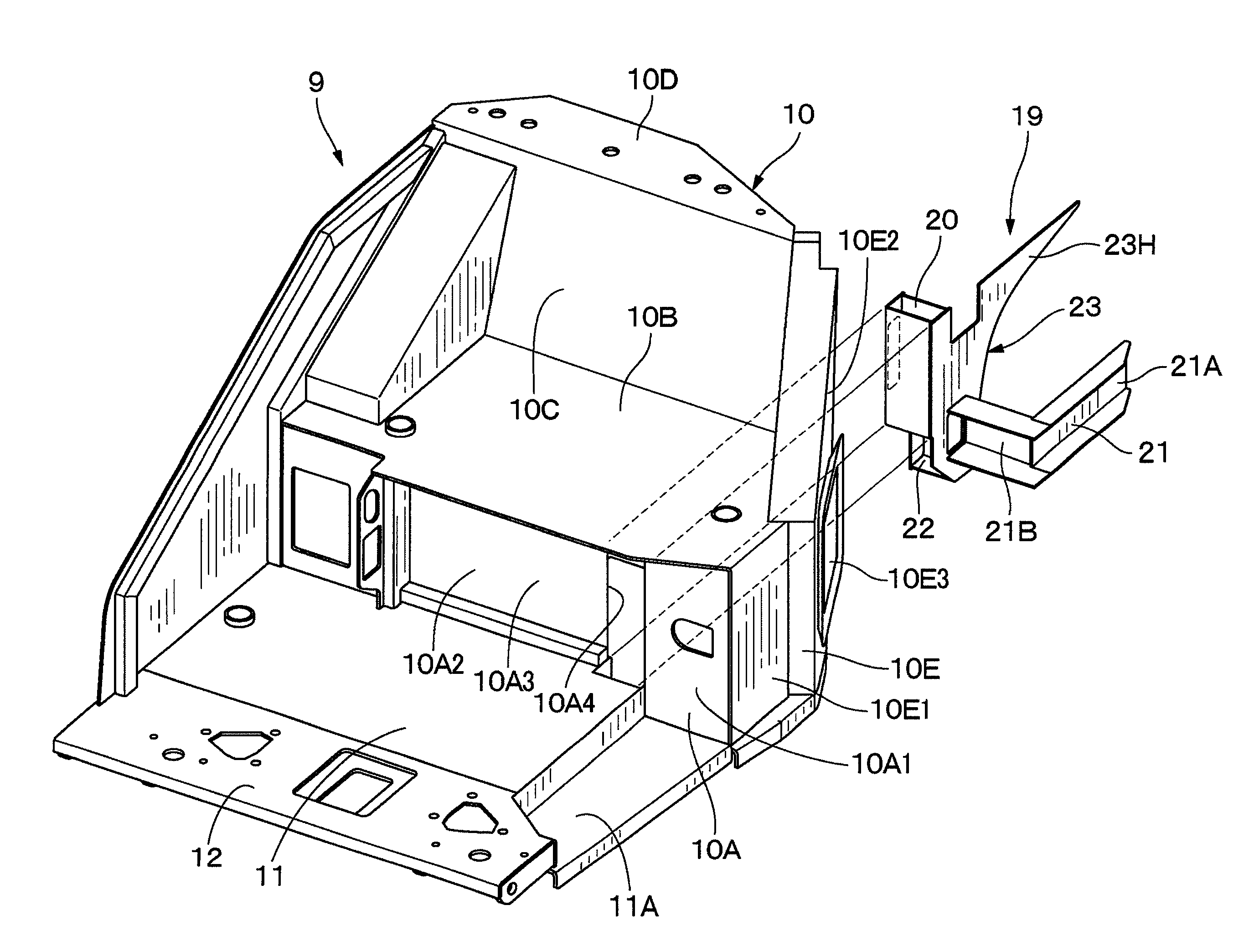
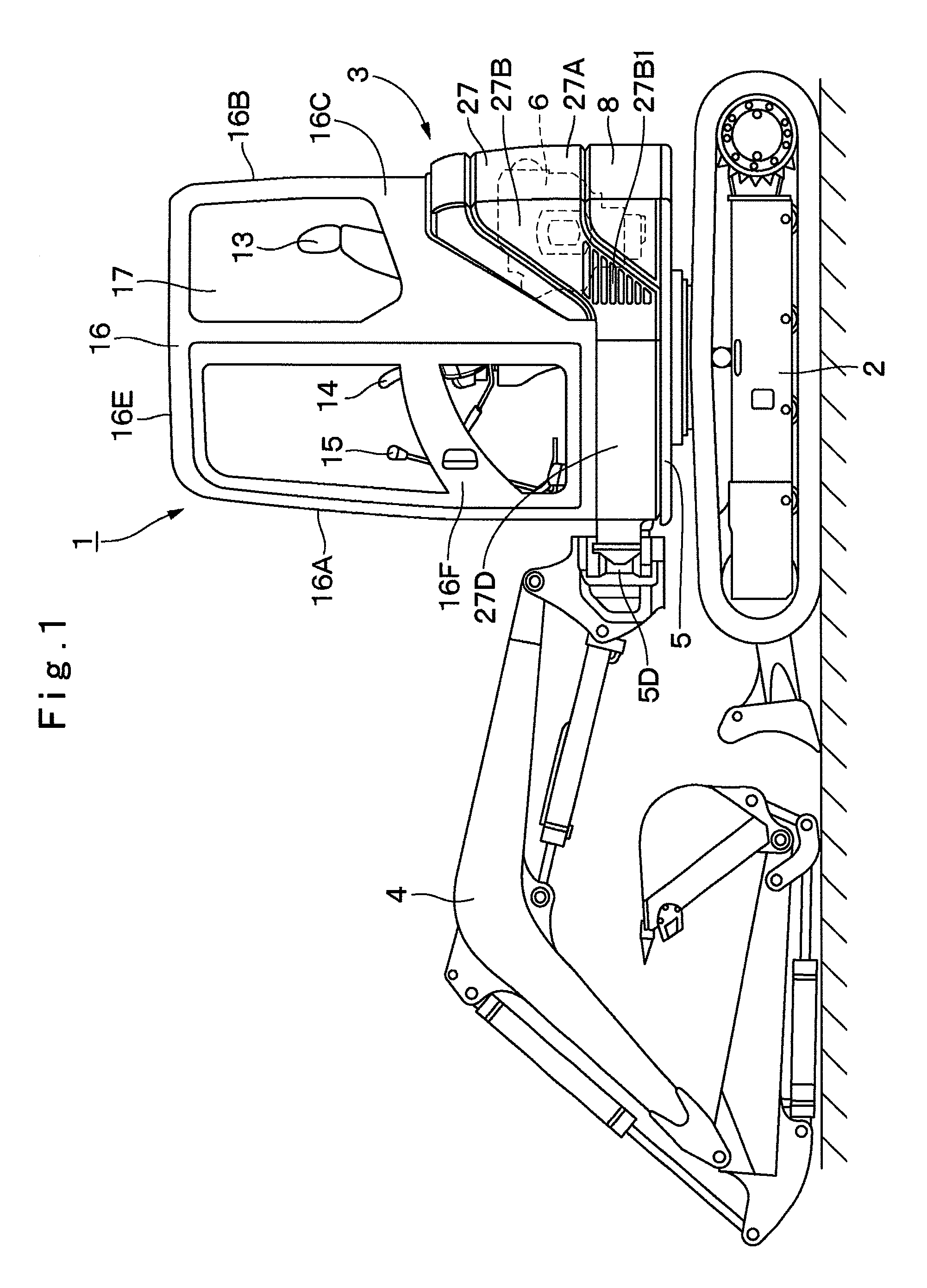
[0034]Hereinafter, a construction machine to be applied to an embodiment in the present invention will be in detail explained with reference to FIG. 1 to FIG. 14, by taking a cab-furnished type hydraulic excavator as an example.

[0035]In FIG. 1, described at 1 is a cab-furnished type hydraulic excavator known as a construction machine to be applied to the present embodiment, and the hydraulic excavator 1 is a small-sized hydraulic excavator called a mini excavator suitable for an operation at a narrow working site. The hydraulic excavator 1 is largely constituted by an automotive lower traveling structure 2, an upper revolving structure 3 which is swingably mounted on the lower traveling structure 2, and a working mechanism 4 provided at the front side of the upper revolving structure 3 in the front and rear directions for performing an excavating operation of earth and sand.

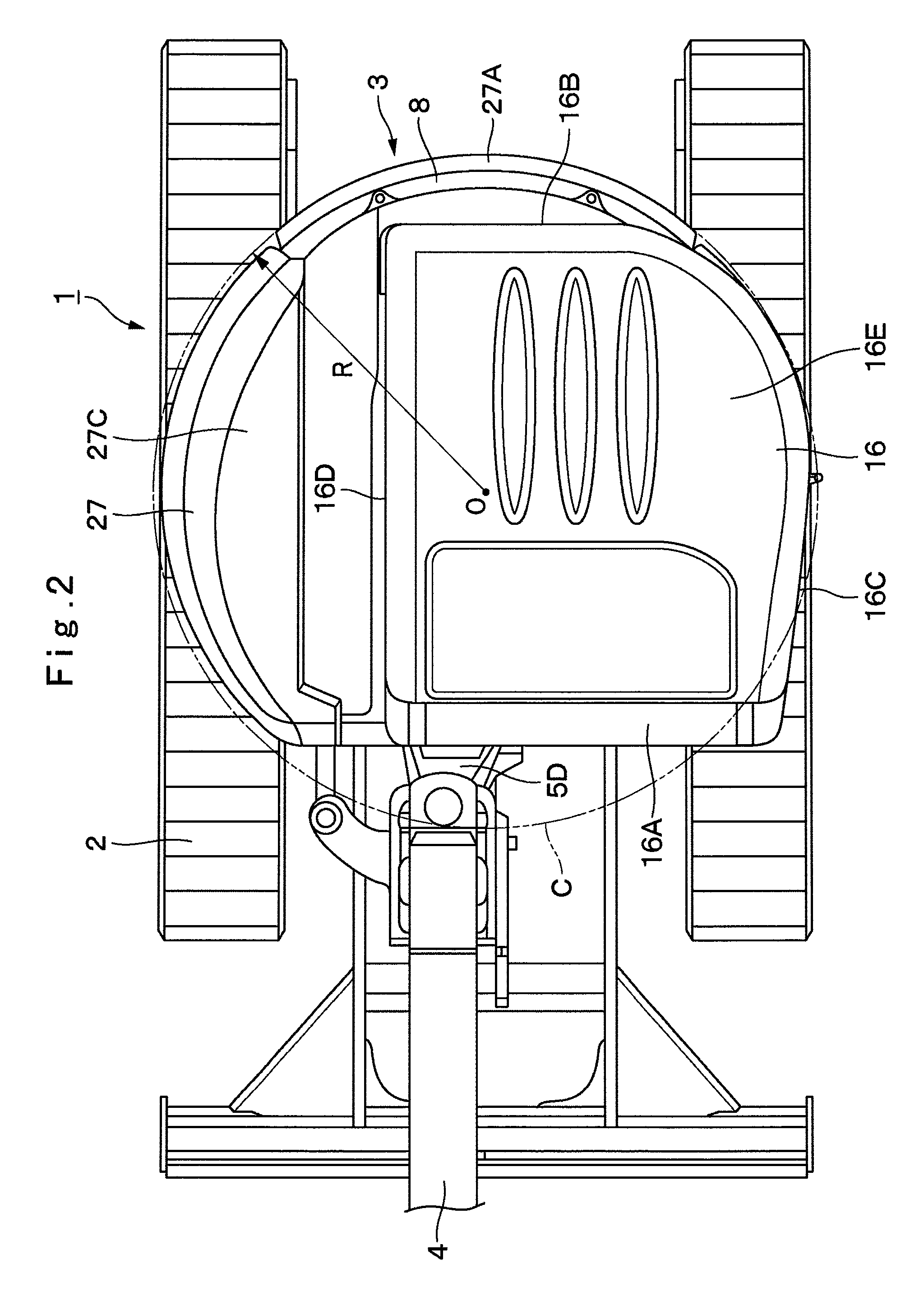
[0036]As shown in FIG. 2, the upper revolving structure 3 has a width dimension in the right and left directio...


PUM


Abstract

A suction duct (19) provided in a floor member (9) comprises an internal air duct portion (20) connected to the internal air inlet port (10A3), an external air duct portion (21) connected to an external air inlet port (10E3), and a common duct portion (22) for connecting the internal air duct portion (20) and the external air duct portion (21) to a blower fan 18B suction side of an air conditioner unit (18). The suction duct is constructed to form a hollow column (23) having a hollow closed section structure with the internal air duct portion and the common duct portion formed integrally in the upper and lower directions. Therefore, the hollow column formed of the hollow closed section structure can increase strength of the floor member as a strong column while circulating internal air between the internal air inlet port and the air conditioner unit.

Description

TECHNICAL FIELD[0001]The present invention relates to a construction machine such as a hydraulic excavator equipped with an air conditioner unit on a floor member thereof.BACKGROUND ART[0002]In general, a hydraulic excavator as a construction machine largely constituted by an automotive lower traveling structure, an upper revolving structure swingably mounted on the lower traveling structure, and a working mechanism liftably mounted at the front side of the upper revolving structure.[0003]The upper revolving structure is provided with a revolving frame serving as a support structure, a floor member provided on the revolving frame and having an operator's seat mounting section at the rear side for mounting an operator's seat and having a foot rest section at the front side on which an operator rests his or her feet, a cab box provided to cover the periphery and the upper side of the floor member for forming an operator's room on the floor member, and an air conditioner unit provided ...

Claims


Application Information

Patent Timeline
Patent Type & Authority Patents(United States)
IPC IPC(8): B60H1/22
CPCE02F9/0858E02F3/325B60H1/00378E02F9/166B60H1/00564B60H1/244B60H1/00E02F9/16
Inventor KIMURA, SHOUGOISHII, HAJIMETABETA, HIROSHI
Owner NIHON KENKI CO LTD
Why Eureka
Try Eureka