
Catalytic combustor and fuel reformer having the same

a technology of catalytic combustor and fuel reformer, which is applied in the direction of catalytic material combustion, combustion types, lighting and heating apparatus, etc., can solve the problem of difficult to allow a fuel to be completely burned, and achieve the effect of improving the performance and efficiency of a fuel reformer, reducing hot spots, and improving the thermal efficiency of a catalytic combustor

Inactive Publication Date: 2013-12-31
SAMSUNG SDI CO LTD
View PDF37 Cites 7 Cited by
  • Summary
  • Abstract
  • Description
  • Claims
  • Application Information

AI Technical Summary

Benefits of technology

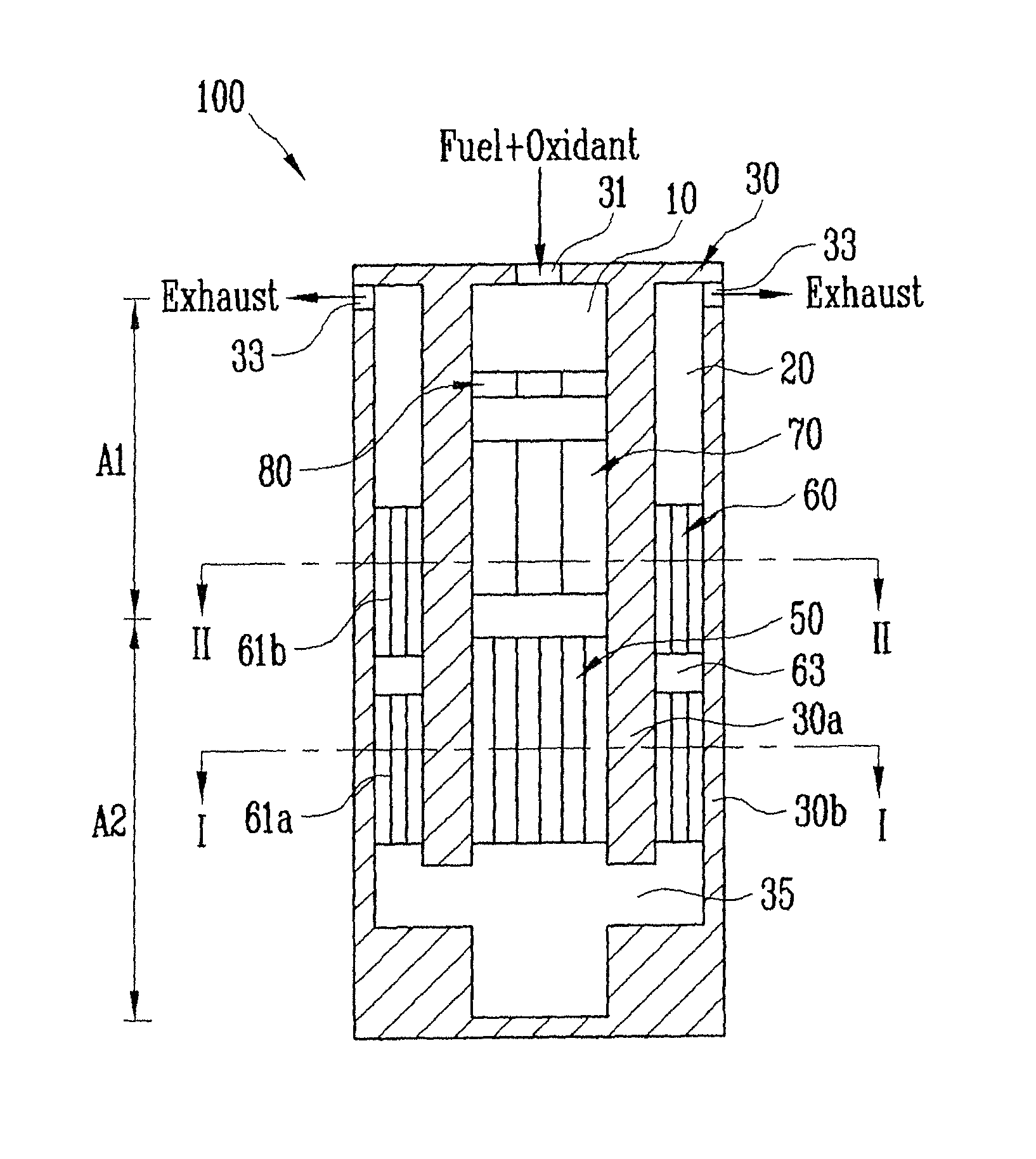
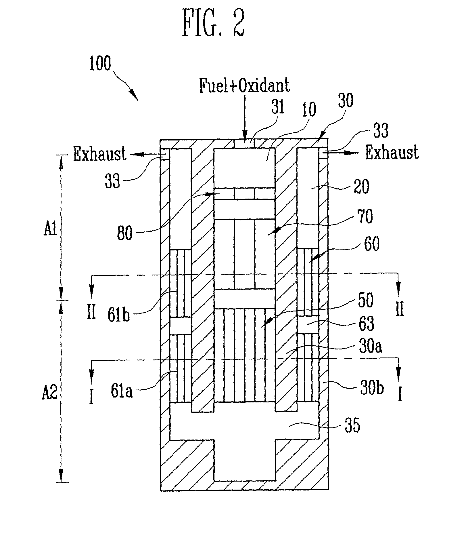
[0008]An aspect of an embodiment of the present invention is directed toward a catalytic combustor capable of inducing the complete oxidation of a fuel and improving the thermal efficiency of a reactor by utilizing a dual oxidation structure.
[0009]Another aspect of an embodiment of the present invention is directed toward a catalytic combustor capable of inducing the complete oxidation of a fuel and improving the thermal efficiency of a reactor by utilizing a dual oxidation structure and a dual fuel structure.
[0025]According to the embodiments of the present invention, a fuel is more completely oxidized in a catalytic combustor. Further, the catalytic combustor allows a thermal gradient to be uniform by using conduction and convection in the dual oxidation structure, so that hot spots are reduced. Accordingly, the thermal efficiency of the catalytic combustor can be considerably improved. Further, although an oxidation catalyst may be used only at a front end in the dual oxidation structure, i.e., a small amount of catalyst is used, the complete oxidation of a fuel can still be easily induced. Further, it is possible to improve the performance and efficiency of a fuel reformer having the catalytic combustor.

Problems solved by technology

However, in the catalytic combustor, it is difficult to allow a fuel to be completely burned as compared with the direct burning type combustor.

Method used


Image

  • Catalytic combustor and fuel reformer having the same
  • Catalytic combustor and fuel reformer having the same
  • Catalytic combustor and fuel reformer having the same

Examples


Embodiment Construction

[0035]In the following detailed description, only certain exemplary embodiments of the present invention have been shown and described, simply by way of illustration. As those skilled in the art would realize, the described embodiments may be modified in various different ways, all without departing from the spirit or scope of the present invention. Accordingly, the drawings and description are to be regarded as illustrative in nature and not restrictive. In addition, when an element is referred to as being “on” another element, it can be directly on the another element or be indirectly on the another element with one or more intervening elements interposed therebetween. Also, when an element is referred to as being “connected to” another element, it can be directly connected to the another element or be indirectly connected to the another element with one or more intervening elements interposed therebetween. Hereinafter, like reference numerals refer to like elements. In the drawin...


PUM


Abstract

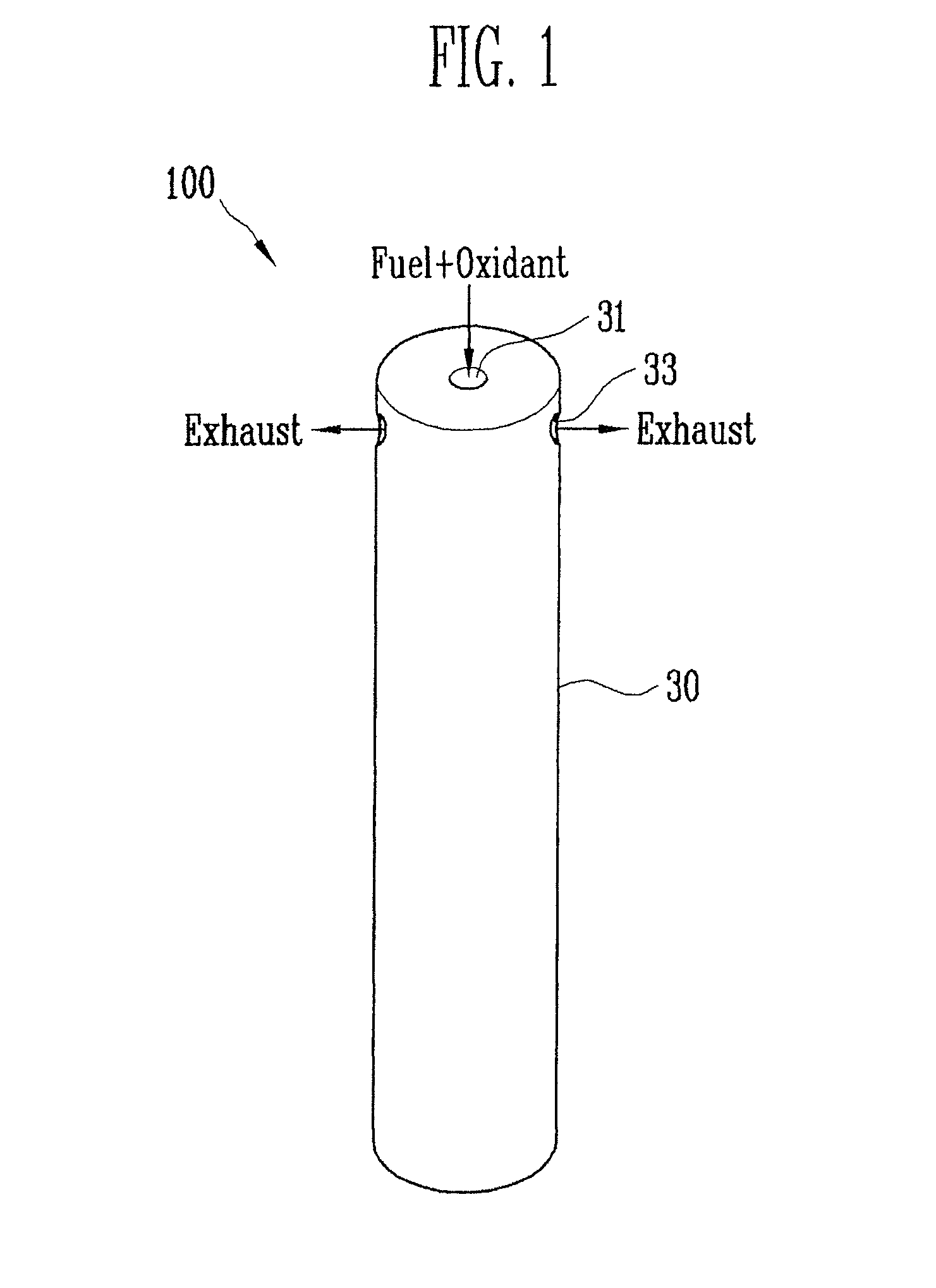
A catalytic combustor and a fuel reformer having the same. The catalytic combustor includes a housing having a cylindrical reaction portion and a second reaction portion surrounding the first reaction portion in a double tube shape. The housing has a first opening for supplying a first fuel and an oxidant to the first reaction portion and a second opening through which an exhaust in the second reaction portion is discharged. The first and second openings are disposed at first sides of the first and second reaction portions, respectively. The first and second reaction portions are connected with each other so that the fluid is communicated with the first and second reaction portions at second sides of the first and second reaction portions. A catalyst is disposed in the first reaction portion, and a mesh layer is inserted into the second reaction portion.

Description

CROSS-REFERENCE TO RELATED APPLICATIONS[0001]This application claims priority to and the benefit of Korean Patent Application No. 10-2009-0046894, filed on May 28, 2009, in the Korean Intellectual Property Office, the entire content of which is incorporated herein by reference.BACKGROUND OF THE INVENTION[0002]1. Field of the Invention[0003]The following description relates to a catalytic combustor capable of inducing oxidation of a fuel and improving the thermal efficiency of a reactor, and a fuel reformer having the same.[0004]2. Description of the Related Art[0005]A combustor is a device that generates heat and high-temperature gas by oxidizing a fuel. The heat and high-temperature gas, generated from the combustor, may be used for reforming reaction of a reformer, preheating of fuel or water, and the like. The combustor may be manufactured in such a manner that allows a fuel sprayed into a combustion chamber to be directly burned, that allows a fuel to be burned through an oxidat...

Claims


Application Information

Patent Timeline
Patent Type & Authority Patents(United States)
IPC IPC(8): B01J8/00
CPCB01J19/2485F23C2900/03002C01B2203/0233C01B2203/066C01B3/34C01B2203/0827C01B2203/0811B01J19/2495F23C13/04B01J2219/00117F23C6/047C01B2203/0822Y02E60/50Y02P20/10H01M8/04
Inventor SON, IN-HYUKSHIN, WOO-CHEOLAHN, JIN-GOOCHOI, JONG-ROCKLEE, SUNG-CHUL
Owner SAMSUNG SDI CO LTD
Learn More