Heat is a critical bottleneck to the performance and reliability of microelectronic circuits and systems.
Therefore, existing thermal management solutions designed for Si and GaAs devices are not adequate for GaN and SiC chips.
Heat extraction is a major bottleneck for microelectronic chips and as such it has generated a lot of R&D efforts from multiple companies.
However, none of these technologies are adequate for wide band gap semiconductors (GaN and SiC) which are generating heat fluxes in excess of 1 kW / cm2 and none simultaneously addresses packaging, interconnection and cooling.
1. K-C Chen et al., Thermal management and novel package design of high power light emitting diodes, National Cheng Kung University, Taiwan, Electronic Components and Technology Conference, 2008. In this paper the authors present a method for cooling high power light emitting diodes (LED) by doing electroless plating of Cu on the backside of the diode (FIG. 1 of their paper shows the cross section of package). This reduces junction temperature by up to 40° C. and thermal resistance by as much as 40%. The disadvantage of this approach is that the authors do not address the interconnection issue between chips. One could use conventional wirebonds which are only applicable to singulated LED chips with fixed chip sizes and thicknesses, but wirebonding techniques cannot be used for high frequency components (due to their parasitic inductance) and are not compatible when trying to combine multiple chips of various sizes and substrate thicknesses in close proximity to each other. In this disclosure, due to the method taught for mounting and backside metalizing the chips, results in a flat surface at the top (independently of the size and thickness of the encapsulated chips) which is used to easily and accurately interconnect the chips.
2. A. A. Ali et al., Notebook computer with hybrid diamond heat spreader, Apple Inc, US Published Patent Application 2008 / 0298021, filed May 31, 2007. The inventors disclose the use of CVD deposited thin film diamond for a heat spreader. The chip is mounted on thin film diamond using a TIM material (solder, thermal grease, phase change epoxy, or thin film metal: Ti / Pt / Au layer). The heat spreader is a thin film diamond, a diamond / copper hybrid, a diamond / aluminum hybrid, an aluminum or copper film. The inventors also show different embodiments of their structure where heat pipes are embedded in the heat sink for increase heat transfer coefficient. This approach presented is not able to meet the 1 kW / cm2 requirement noted above and is less effective compared to approach disclosed herein for all values of heat transfer coefficient. Furthermore, the approach taught herein offers a better reduction of the chip's junction temperature and it does not require expensive and high temperature fabrication processing steps (CVD deposition of thin film diamond). Finally the chip interconnection is an issue not addressed in this patent application by A. A. Ali et al.
3. R. Feeler et al., Next-generation microchannel coolers, Northrop Grumman, Proceedings of SPIE 2008. The authors present a micro-channel cooler for LED arrays using Low Temperature Co-Fired Ceramic (LTCC) material. They use a heat sink made out of AlN, BeO or CVD diamond under the LED chip and then connect this to the LTCC micro-channel. The CTE of LTCC is close to GaAs and InP so the authors are using hard solder (AuSn) to mount the LED on the cooler. The LTTC addresses one major failure mechanism of copper micro-channels, which is their erosion when they are exposed to high water speeds. However, this approach has some disadvantages which are addressed by the present disclosure.
First the distance between the backside of the chip and the cooling water is over 300 microns. It is critical to minimize this distance and in our approach the cooling air or liquid can be brought to very close proximity to the backside of the wafer due to the method the heat sink is deposited. In addition to that LTCC has worse thermal conductivity (3.5 W / mK) compared to AlN (150 W / mK) and copper (400 W / mK) which are used in the resent disclosure. This is the reason the authors need to use an additional thin film diamond or AlN heat sink under the LED chip. This is unnecessary in the design disclosed herein. The chip mounting still requires solder which adds a high thermal resistance layer. Finally, chip interconnection, which is extremely critical for all high frequency applications, is not addressed.
4. J. Oh et al., Package-on-package system with heat spreader, US Published Patent Application 2009 / 0294941, filing date: May 30, 2008. The inventors present a package-on-package system that includes mounting the chip on a base substrate, positioning an interposer over the chip and forming a heat spreader around the chip and the interposer. Their approach focuses on multi-stacked chips and extracting heat from inside the stack by inserting the heat spreader between the packages as well as at the top of the module. The heat spreader surrounds the entire chip. However this approach has disadvantages.
First it does not offer direct connection to the bottom of the chip (which is the primary area of heat dissipation coming from the active device junction). In contrast, heat is removed from the edges of the chip where solder is used to connect the heat sink to the chip. This is a very inefficient way to remove heat and definitely inadequate to handle the heat flow of wide band-gap components. Furthermore, the fact that the heat sink surrounds each chip makes integration of multiple chips difficult since significant component area around each chip is lost. Interconnection between different chips is impossible unless they are combined in a single heat sink. In this case a redesign of the heat sink will be necessary every time different chips are cooled.
5. M. J. Schaenzer et al., Thermally coupling an integrated heat spreader to a heat sink, US Published Patent Application 2006 / 0027635, filing date: Aug. 9, 2004. The inventors present a mounting method where the base of the heat sink is selectively plated with solder and connected to a heat spreader plated with Au. The heat sink is connected to the top of the chip. This approach is close to conventional cooling methods. The disadvantages of this is that it requires a high thermal resistance TIM material (solder) to transfer heat from the chip to the heat sink, it can be used for a single chip only (not applicable to 3D multi-layer systems or multiple chips integrated in a single system) and it offers no solution for interconnecting multiple chips especially for high frequency applications.
6. CREE Inc is listed as the assignee of several US patent applications related to cooling of semiconductor chips: (i) US Published Patent Application 2009 / 0134421 by G. H. Negley, “Solid metal block semiconductor light emitting device mounting substrates and packages”; (ii) US Published Patent Application 2008 / 0099770 by N. W. Mendendorp, “Integrated heat spreaders for light emitting devices and related assemblies”; (iii) US Published Patent Application 2007 / 0247851 by R. G. Villard, “Light emitting diode lighting package with improved heat sink”; and (iv) US Published Patent Application 2006 / 0292747 by B. P. Loh, “Tops surface mount power light emitter with integral heat sink”. All these are more traditional cooling approaches and rely on mounting the LED chips on various heat sinks.
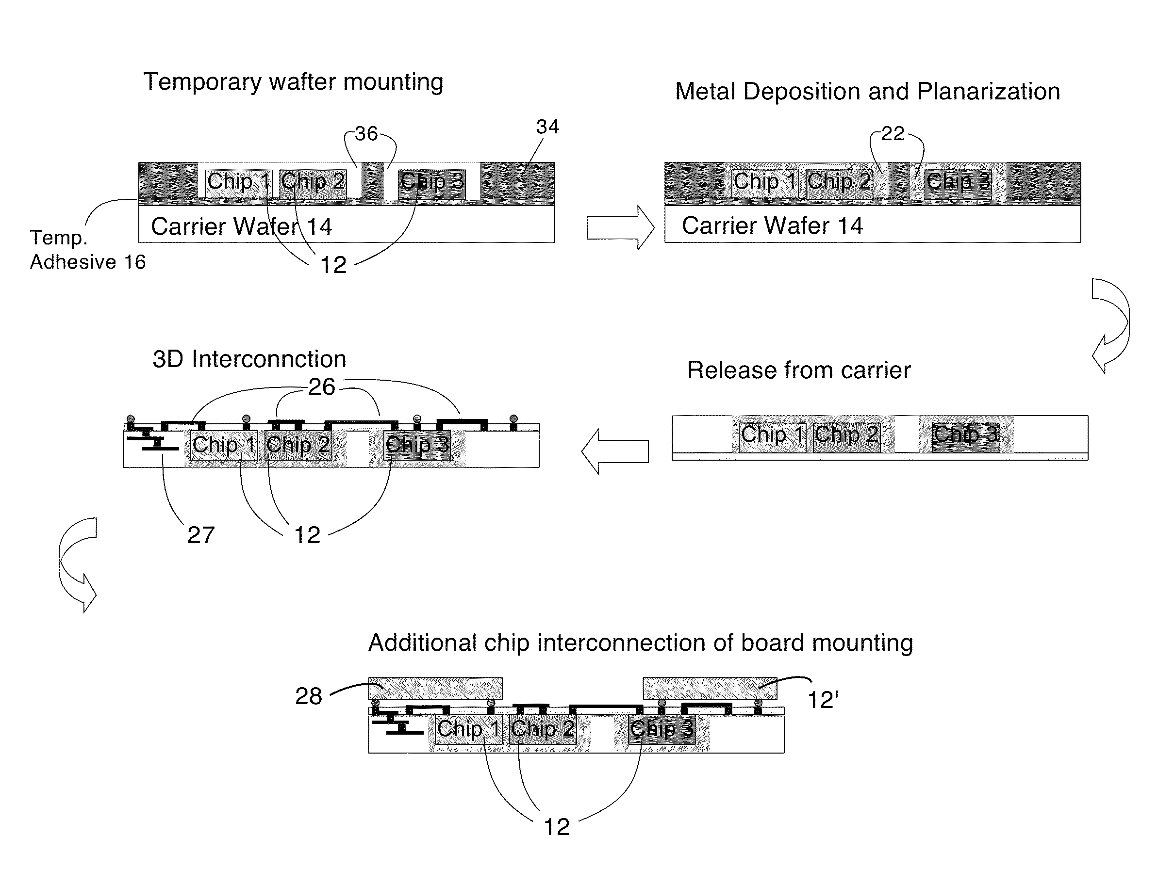
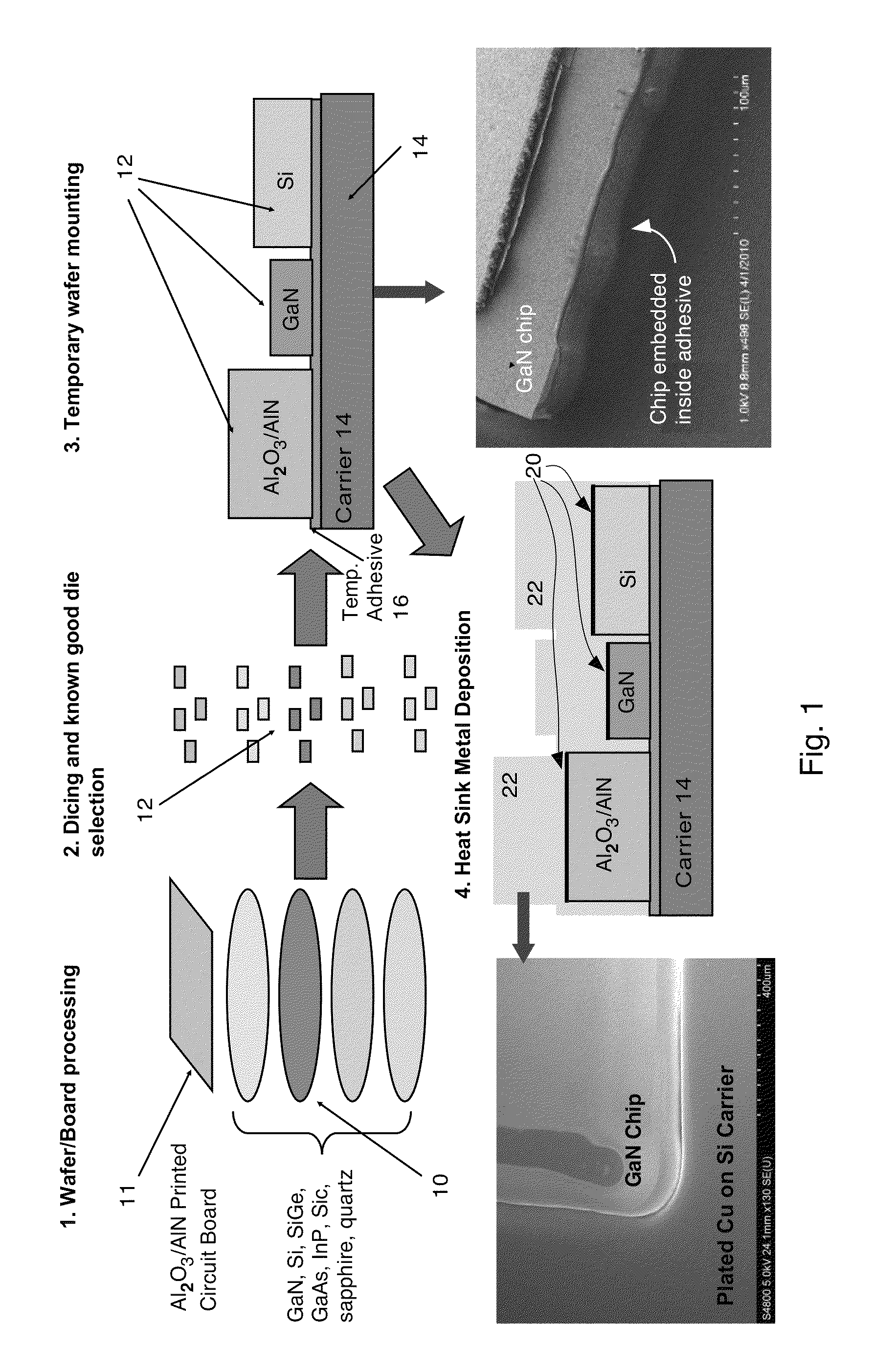
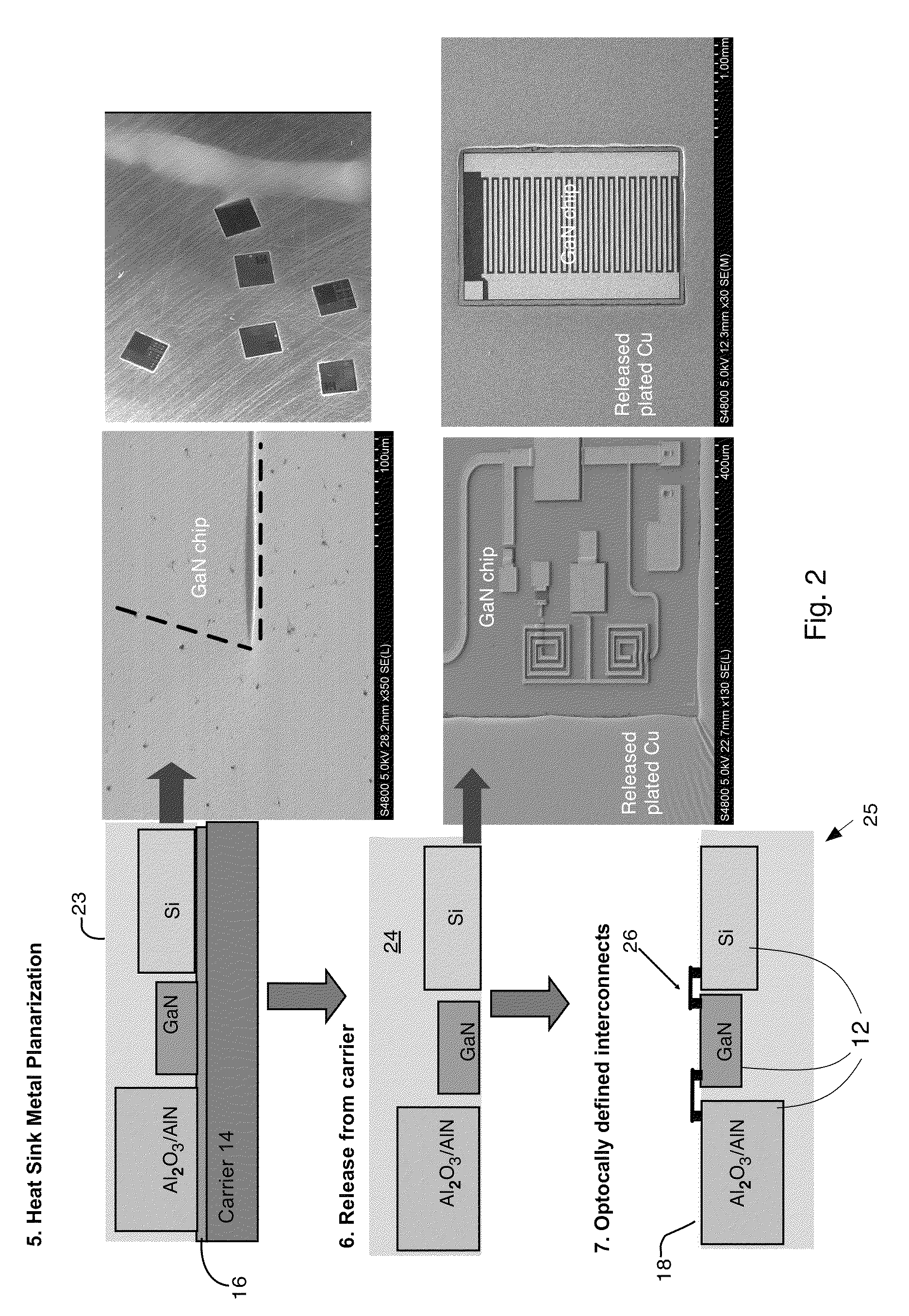
7. B. D. Raymond, “Wafer scale integrated thermal heat spreader”, M / A-COM Inc, US Published Patent Application: 2009 / 0108437, filing date: Oct. 29, 2007. The author discloses a method of creating a heat sink by backside metallization of a wafer. This metallization is realized with composite electroplating of various metallic compounds with variable CTE. Some examples are Cu-Diamond, Cr-Diamond, or metallic compounds with Be, BeO and carbon nano-tubes. After the wafer is backside metalized, the individual chips are diced. The disadvantages of this disclosure are that it metalizes the entire wafer and it does not offer any method for interconnecting the chips. In our case, only operational and pre-tested chips (known good die), from a single or different wafers, are temporarily mounted on a carrier. (This is significant because if the fabrication process on the entire wafer is low-yield, the prior art by Raymond will still metalize the entire backside of the wafer and result in a major cost increase). Then their backside surface is metalized and upon release from the carrier we have a heat sink that serves as the interposer layer upon which we can interconnect the chips and also mount additional chips, integrate antennas etc. Therefore, unlike all known prior art, our approach extends the backside metallization to a complete packaging / integration / cooling solution.
8. S. Z. Zhao et al, Flip chip package including a non-planar heat spreader and method of making the same, Broadcom Inc, US Published Patent Application: 2006 / 0091509, filing date Nov. 3, 2004. The author discloses a traditional cooling approach focusing on flip-chip interconnected packages and the formation of a cavity on the heat sink which allows for easier integration of the chip. The disadvantages of this approach are that it requires special machining of the heat sink and it still needs TIM materials for connecting the chip to the heat sink.
9. T. W. Chao, Heat spreader for a multi-chip package, Intel Inc., US Published Patent Application: 2008 / 0128897. Similar to prior art above, this is a more conventional approach focusing on flip-chip mounted chips.
10. D. Lu et al, Microelectronic package having direct contact heat spreader and method of manufacturing same, Intel Inc., US Published Patent Application: 2007 / 0075420. This application is similar to the application of Raymond mentioned above. The main difference is that the devices are flip-chip mounted active face down to a board and then metalized from the back. Again metallic compounds are proposed for better CTE matching. Compared to the M / A-COM application this does offer the advantage of processing known-good-die but it requires flip-chip bonding on a board. This is a reliability concern since the solder bumps and the underfil material used have higher thermal resistance. Compared to this prior art, the advantage of the present approach as disclosed herein is that it offers a superior solution in interconnecting the chip to other devices and in integrating into a 3D system.
11. J. Noqil, Dual side cooling integrated power device module and methods of manufacture, U.S. Pat. No. 7,777,315, Aug. 17, 2010. This disclosure power combines multiple chips and offers a path for dual side cooling. However, the parts are integrated together using a molding material, some form of resin, which is a low thermal conductivity material.
This approach cannot be extended to high frequency power devices (due to the epoxy that has to surround the interconnects) and also is limited with respect to its heat flux removal rate by the thermal conductivity of the epoxy which is not too high.
The approach cannot be extended to 2D scanning arrays.
As this relies on waveguides for power combining and radiation it will be challenging to fit within the 1.6 mm spacing requirement for W-band arrays.

