Brick bracket for installation of a ledger on the brick facing or veneer of a structure and associated methods for the installation of the brick bracket on the brick facing

a technology of brick bracket and ledger, which is applied in the direction of washstands, lighting support devices, building repairs, etc., can solve the problems of difficult and expensive process, brick veneer cannot support additional loads, and only support its own weigh

Inactive Publication Date: 2014-01-07
SPYROU ALEXIS
View PDF63 Cites 28 Cited by
  • Summary
  • Abstract
  • Description
  • Claims
  • Application Information

AI Technical Summary

Benefits of technology

[0010]An object of the invention is to provide means by which the deck can be connected to the framework of the building in a simple manner without the need for incident costs and labor as described above.
[0011]A further object of the invention is to provide such means by which the ledger can be attached to the framework without risk of applying forces to the brick veneer.
[0016]The method of the invention is very simple and requires no complexity in the installation of the brackets to the framing and it also assures that no bending forces will be applied to the underlying bricks of the brick veneer due to the weight of the deck and the use to which it is put.

Problems solved by technology

A problem exists as regards how to connect a load bearing member to a building having a brick facing or veneer.
Most Building Codes specify that brick veneer can only support its own weight and cannot support additional loads, such as those from an outside structure such as a deck or roof system.
This presents a problem when it is desired to build a deck on a house with a brick veneer as it is necessary to support a ledger at the side of the house, that serves to support the joists of the deck and resists the weight of the deck.
Normally, the bricks must be removed in the area of the ledger and supported from above which is a difficult and expensive process.
Furthermore this can still lead to application of load on the bricks of the brick veneer because the bolts deflect under the load.
This is costly and also lacks attachment of the deck to the building.
All of these solutions create additional engineering material and labor costs and are difficult to implement.

Method used


Image

  • Brick bracket for installation of a ledger on the brick facing or veneer of a structure and associated methods for the installation of the brick bracket on the brick facing
  • Brick bracket for installation of a ledger on the brick facing or veneer of a structure and associated methods for the installation of the brick bracket on the brick facing
  • Brick bracket for installation of a ledger on the brick facing or veneer of a structure and associated methods for the installation of the brick bracket on the brick facing

Examples


Embodiment Construction

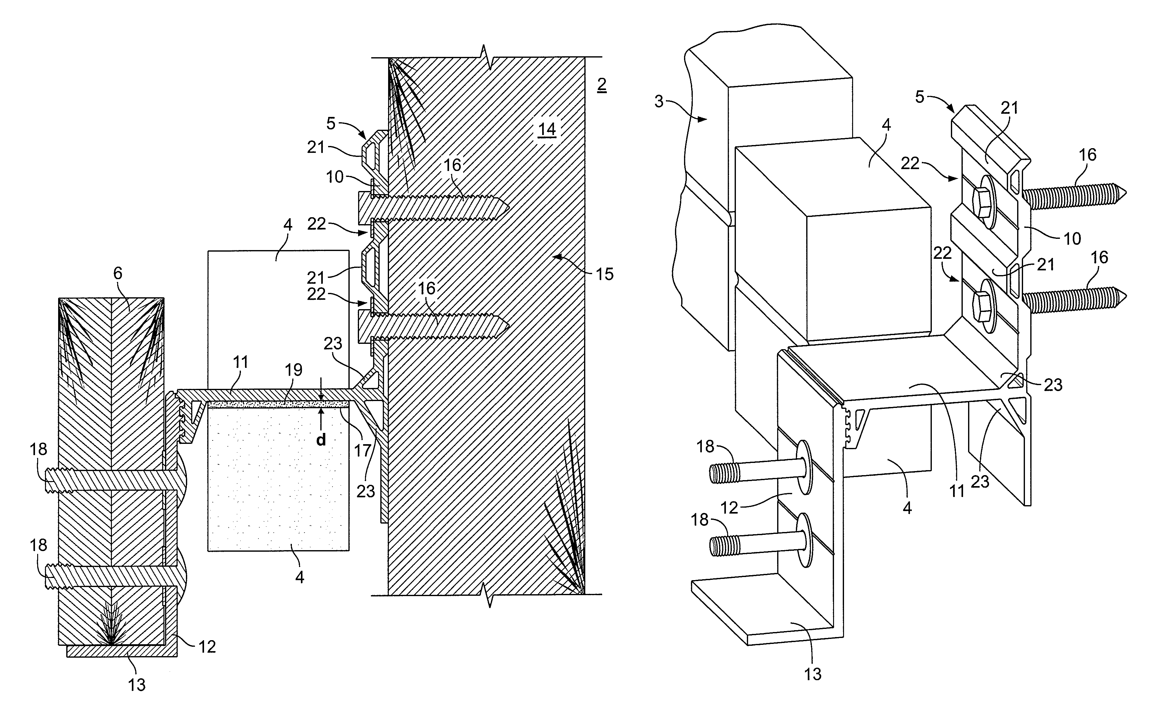
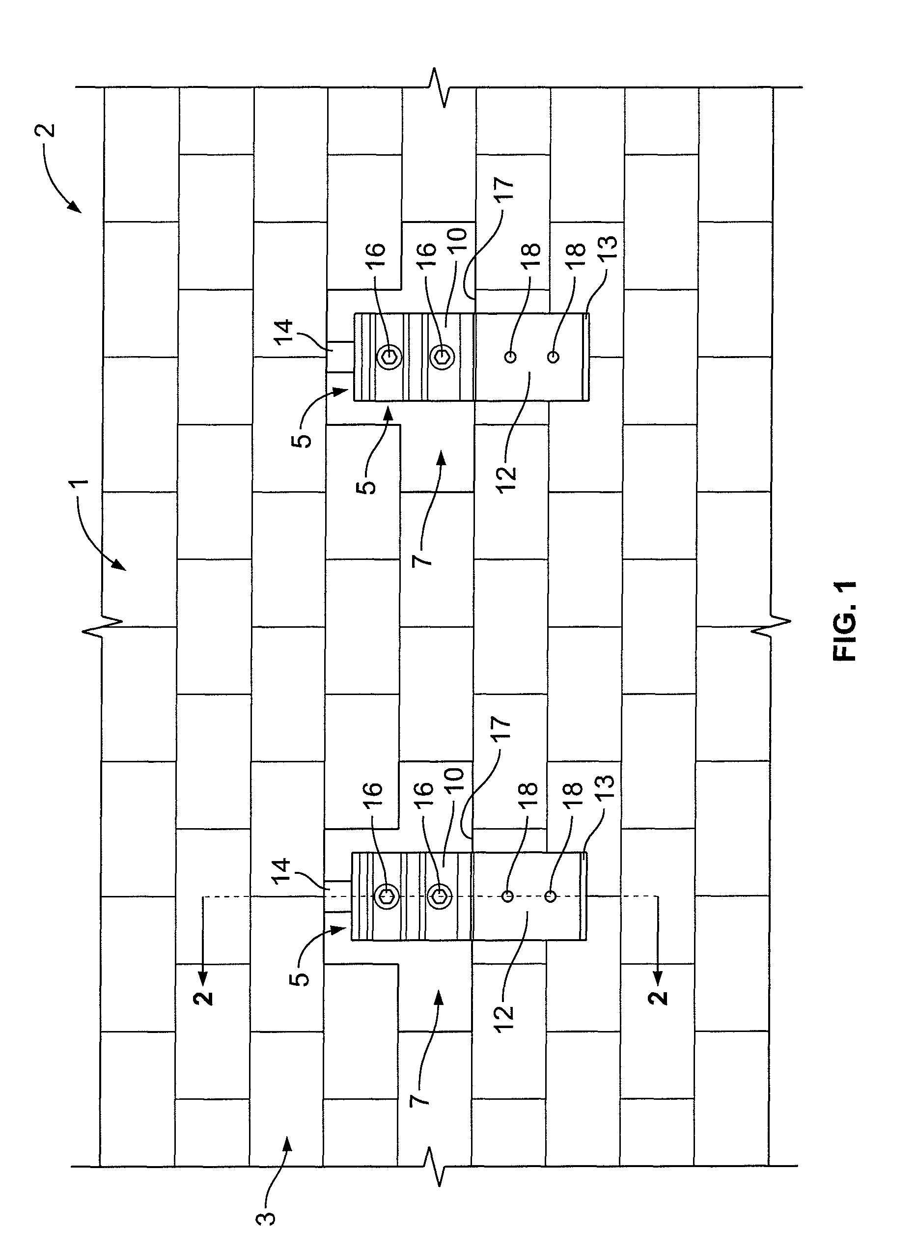
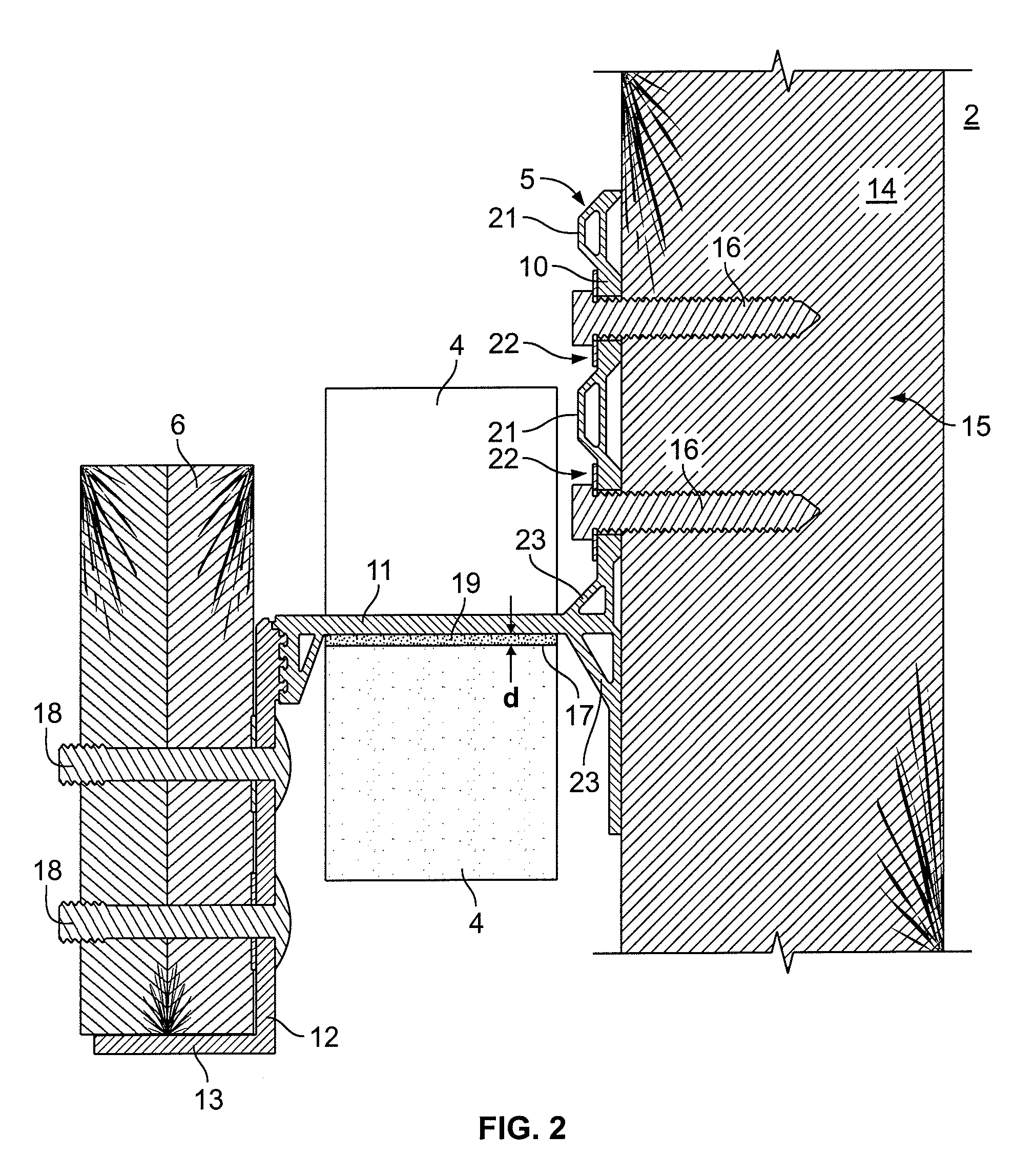
[0021]FIG. 1 shows a portion of a wall 1 of a building 2 such as a house. The wall 1 has a brick facing or veneer 3 composed of rows of bricks 4 placed one above the other.

[0022]The invention is based on a construction by which a structure such as a deck (not shown) can be attached to a building. Although the invention will be described in relation to the attachment of a deck to the building it is only by way of example and other structures can be attached within the contemplation of the invention.

[0023]Since numerous Building Codes prohibit the application of load to the brick facing or veneers of the building 1 to the invention provides a unique way in which the deck can be attached to the building without imposing any load upon the brick facing. In this regard, the invention provides a plurality of brackets 5 spaced longitudinally along the line of bricks attached to the building and adapted to support the ledger 6 which extends along the length of the building over a distance co...


PUM


Abstract

A brick bracket which is installed in a recess provided by removal of brick of a brick veneer in order to be attached to studs of a framework of the building without contacting the bricks. The brick bracket has a front wall which extends outwardly and covers the brick facing and carries carriage bolts to which a ledger can be affixed such that the ledger is able to support an attached structure so that the brick bracket will not apply any force to the bricks of the brick facing.

Description

CROSS RELATED APPLICATION[0001]This application is a continuation of Provisional Application Ser. No. 61 / 183,740 filed Jun. 3, 2009 and claims the priority thereofFIELD OF THE INVENTION[0002]The invention relates to a bracket referred to as a brick bracket for the installation of a ledger at the surface of a brick facing or veneer of a structure such as a building.[0003]The invention also relates to a method for the installation of such a brick bracket.BACKGROUND[0004]A problem exists as regards how to connect a load bearing member to a building having a brick facing or veneer. Most Building Codes specify that brick veneer can only support its own weight and cannot support additional loads, such as those from an outside structure such as a deck or roof system.[0005]This presents a problem when it is desired to build a deck on a house with a brick veneer as it is necessary to support a ledger at the side of the house, that serves to support the joists of the deck and resists the weig...

Claims


Application Information

Patent Timeline
Patent Type & Authority Patents(United States)
IPC IPC(8): E04B2/30E04B1/38
CPCE04B1/003E04B1/40E04B2/56E04B2001/405E04B2002/565E04F13/142E04B2001/389E04B1/388
Inventor SPYROU, ALEXIS
Owner SPYROU ALEXIS
Why Eureka
Try Eureka