
Gate driver and method for repairing the same

a technology of a driver and a gate, which is applied in the field of lcd driving circuits, can solve the problems of not being able to enable the stb>104/b> stage and not being able to enable the 5sup>th/sup>stage stb>105/b> to output a scan puls

Active Publication Date: 2014-01-07
LG DISPLAY CO LTD
View PDF18 Cites 6 Cited by
  • Summary
  • Abstract
  • Description
  • Claims
  • Application Information

AI Technical Summary

Benefits of technology

The present invention provides a gate driver and a method for repairing it that can still operate even if some stages are defective. The gate driver has a repair line that is connected to the first output line, and a repair scan pulse generator that can provide repair scan pulses to the repair line. This invention enables faster and more efficient repairing of defective stages in semiconductor devices.

Problems solved by technology

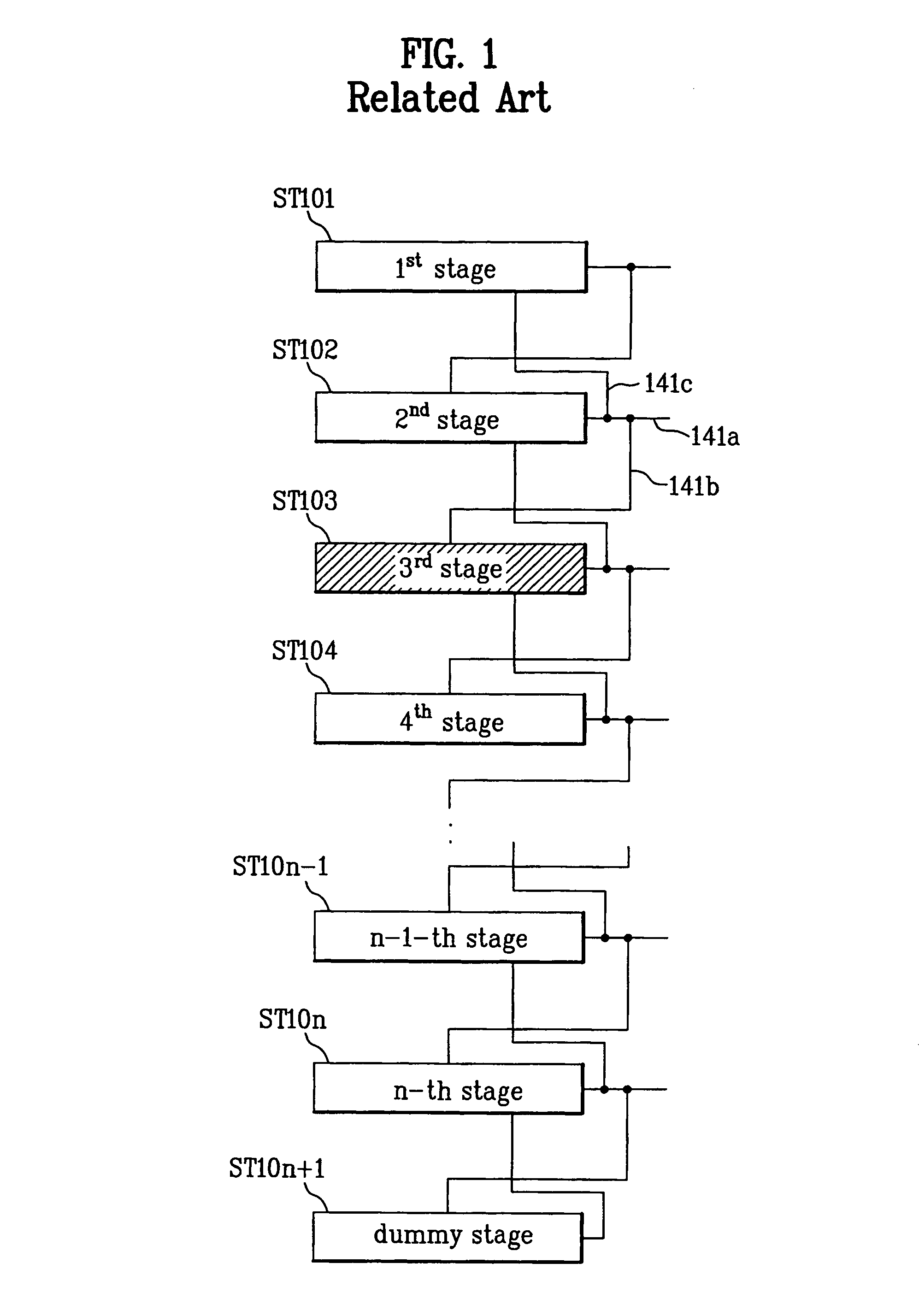
If a defect occurs in one of the stages ST101˜STn+1 such that the defective stage cannot be operated, none of the stages following the defective stage will be able to output a scan pulse.
However, because the 3rd stage ST103 has been rendered inoperable due to a malfunction as described above, the 4th stage ST104 is not enabled to output a scan pulse.
However, since the 4th stage ST104 does not output a scan pulse because of the failure of the 3rd stage, the 5th stage ST105 cannot be enabled.

Method used


Image

  • Gate driver and method for repairing the same
  • Gate driver and method for repairing the same
  • Gate driver and method for repairing the same

Examples


first embodiment

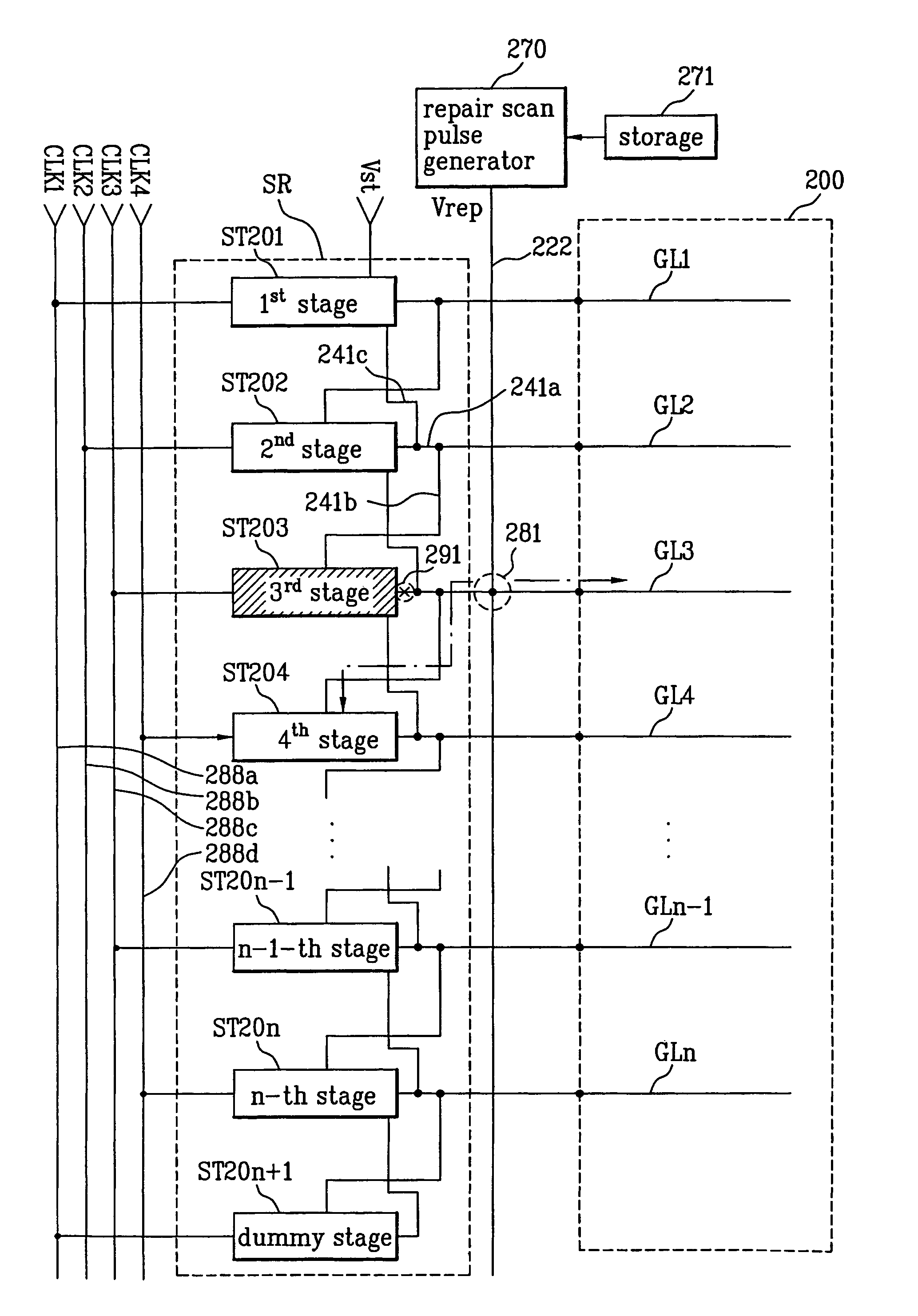
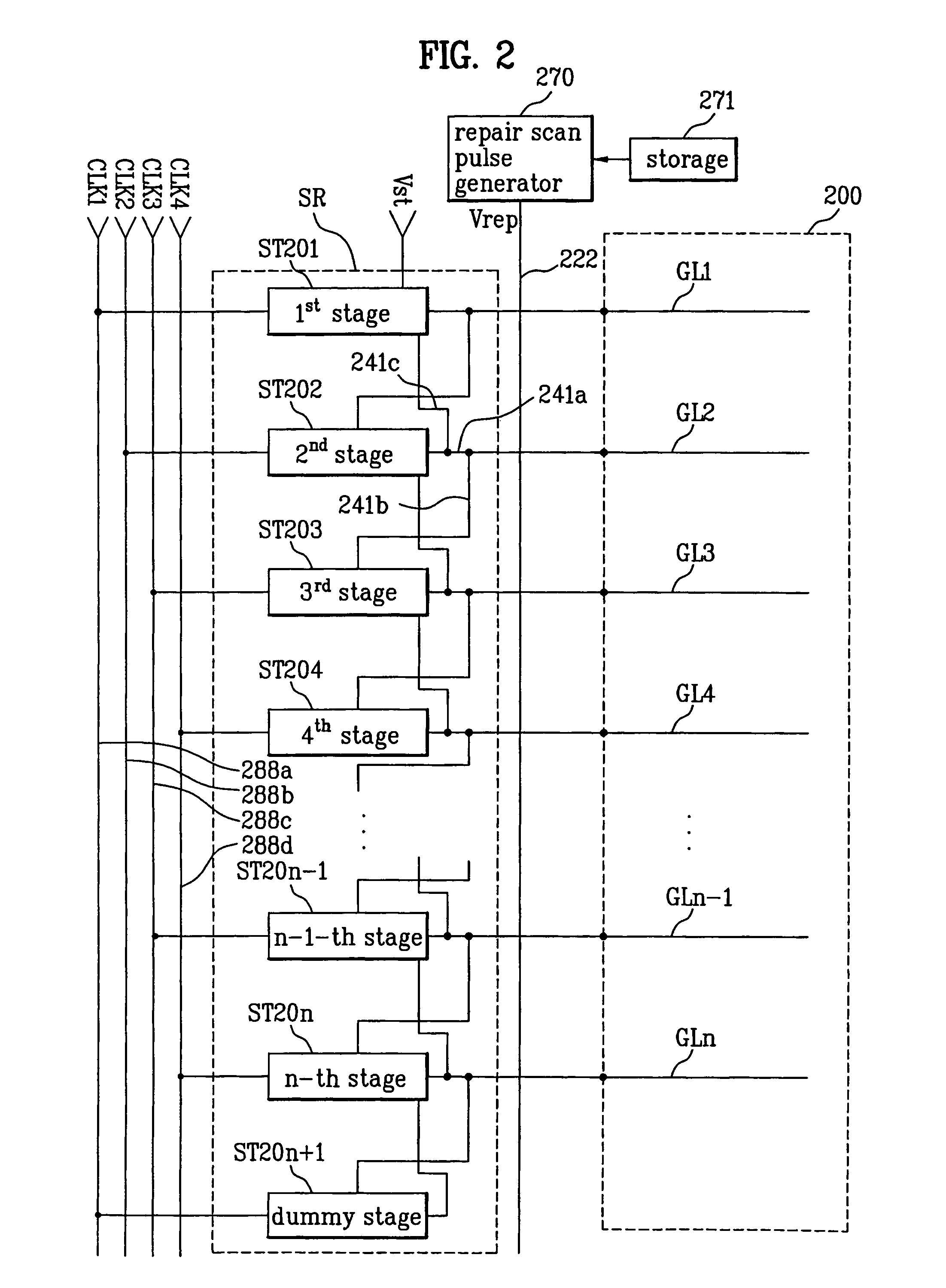
[0040]FIG. 2 illustrates a gate driver according to the present invention.

[0041]As shown in the drawings, the gate driver includes: a shift register SR including a plurality of stages having a plurality of first output lines 241a; a repair line 222 which is arranged such that the repair line 222 crosses each of the first output lines 241a; a storage device 271 for storing information identifying a position of a certain stage; and a repair scan pulse generator 270 for providing repair scan pulses Vrep to the repair line 222 on the basis of the information stored in the storage device 271.

[0042]Hereinafter, the above elements will be described.

[0043]The shift register SR includes 1st to nth stages ST201˜ST20n and a dummy stage ST20n+1. The shift register stages (ST201˜ST20n+1) sequentially generate output scan pulses to be supplied a display unit 200 of a liquid crystal display (LCD) panel. The 1st to nth stages ST201˜ST20n (i.e. not including the dummy stage ST20n+1) each provides sc...

second embodiment

[0085]A description for a gate driver according to the present invention is provided hereinafter with reference to FIG. 6.

[0086]The gate driver according to the second embodiment is configured such that gate lines of two gate drivers of FIG. 2 are correspondingly connected to each other.

[0087]A first shift register SR_R is connected to one ends of gate lines GL1˜GLn included in a display unit 600, through first output lines 641a_L. The first output lines 641a_L cross with repair line 666_L positioned thereon.

[0088]The first shift register SR_L includes a dummy stage ST60n+1_L, and a plurality of stages ST601_L˜ST60n_L, which are connected to ends of the gate lines GL1˜GLn.

[0089]One end of the repair line 666_L is connected to the repair scan pulse generator 670_L. The repair scan pulse generator 670_L controls a timing of outputting the repair scan pulse Vrep based on information stored in a storage device 671_L.

[0090]On the other hand, a second shift register SR_R is connected to a...


PUM


Abstract

A gate driver and a method for repairing the same are disclosed. The gate driver includes a shift register including a plurality of stages each having a respective one of a plurality of first output lines; at least one repair line connectable to the first output lines; a storage device to store information therein to identify a position of a certain stage of the plurality of stages; and a repair scan pulse generator to provide repair scan pulses to the repair line based on information stored in the storage device.

Description

[0001]This application claims the benefit of Korean Patent Application No. 2005-0119372, filed on Dec. 8, 2005 which is hereby incorporated by reference for all purposes as if fully set forth herein.BACKGROUND OF THE INVENTION[0002]1. Field of the Invention[0003]The present invention relates to an LCD driving circuit, and more particularly, to a gate driver capable of repairing defective stages, and a repairing method thereof.[0004]2. Discussion of the Related Art[0005]A Liquid Crystal Display (LCD) device displays images by controlling light transmittance of liquid crystal using electric fields. The LCD device includes a liquid crystal display panel in which pixels are arranged in a matrix format and driving circuits for driving the LCD panel.[0006]The LCD panel is configured such that a plurality of gate lines and a plurality of data lines orthogonally cross each other to define pixel areas within the crossings of the gate lines and the data lines. The LCD panel includes pixel ele...

Claims


Application Information

Patent Timeline
Patent Type & Authority Patents(United States)
IPC IPC(8): G09G3/36
CPCG11C19/00G09G3/3677G09G2330/08G11C19/28G09G3/36G02F1/133G09G3/20
Inventor CHO, NAM WOOKYOON, SOO YOUNG
Owner LG DISPLAY CO LTD
Learn More