Fluidising apparatus with swirl-generating means

a technology of swirl generation and swirling, which is applied in the direction of chemistry apparatus and processes, circuit elements, thin material processing, etc., can solve the problems of increasing the design of the pressure vessel, the requirement of large units, and the discharge duct always within the slurry du

Inactive Publication Date: 2014-01-14
CAMERSON INT CORP
View PDF43 Cites 4 Cited by
  • Summary
  • Abstract
  • Description
  • Claims
  • Application Information

AI Technical Summary

Benefits of technology

[0016]Compared with the prior art apparatus, fluidising apparatus according to the present invention can have smaller inlet and discharge nozzles, avoid bridging of solids in the vessel, be capable of using any fluid as a driving force, be easily accessible and economically viable to replace. It can also be provided with a sacrificial transport outlet in the form of a discharge duct, which avoids errosional damage to pressure vessel components.

Problems solved by technology

A particular disadvantage of the fluidising units described in the above mentioned patents is that the discharge duct is always within the slurry duct.
This can lead to a requirement to have large units and in particular large nozzles in pressure vessels etc.
The larger the dimension of the fluidising unit the more demanding the design of the pressure vessel becomes.
It has also been observed in practice that a large fluidising unit installed inside a pressure vessel can cause a hold-up of material on its top or within the annulus, created by the fluidising unit and its pressure vessel, by the formation of a bridge of solids.

Method used


Image

  • Fluidising apparatus with swirl-generating means
  • Fluidising apparatus with swirl-generating means
  • Fluidising apparatus with swirl-generating means

Examples


Embodiment Construction

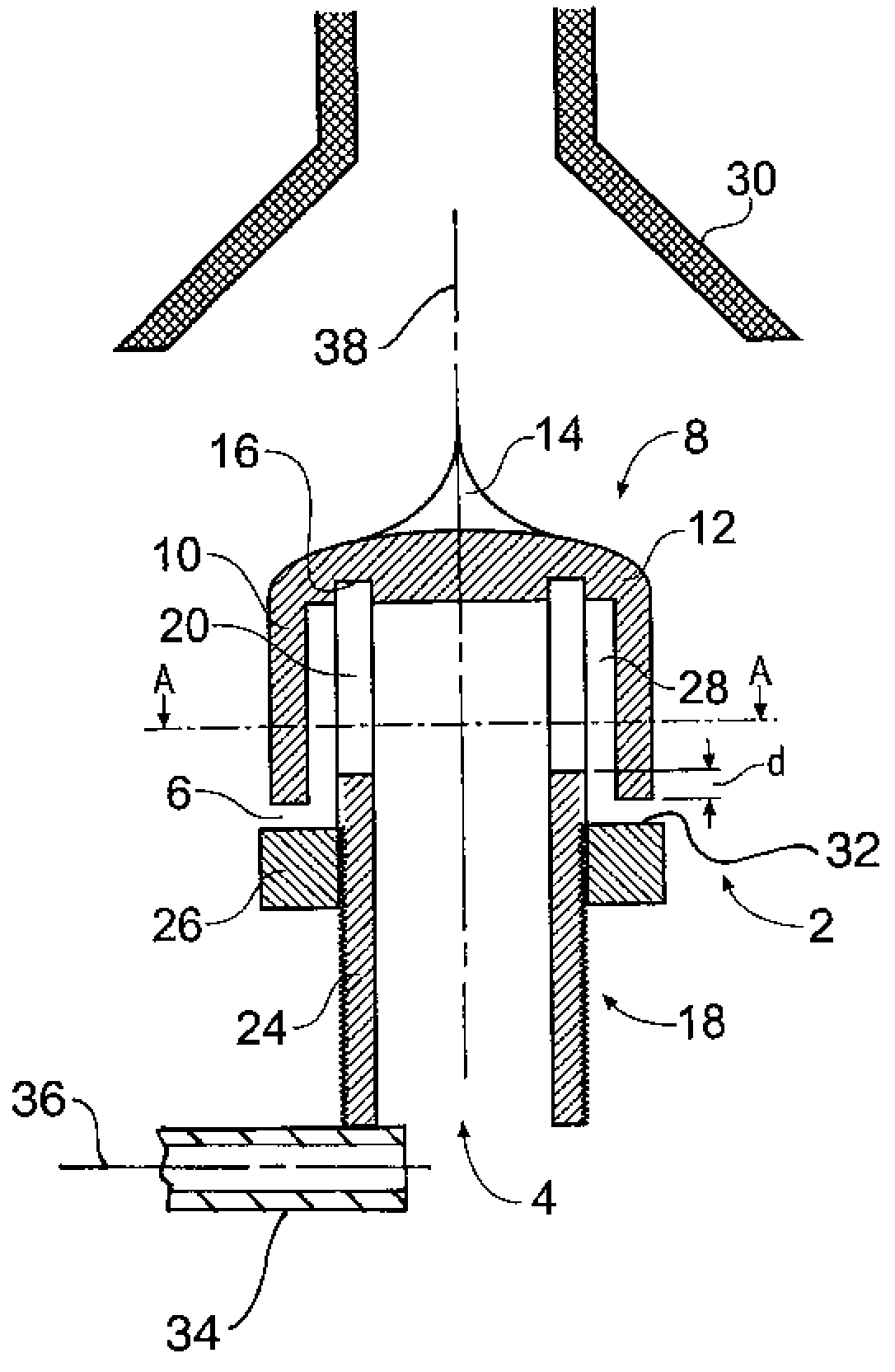
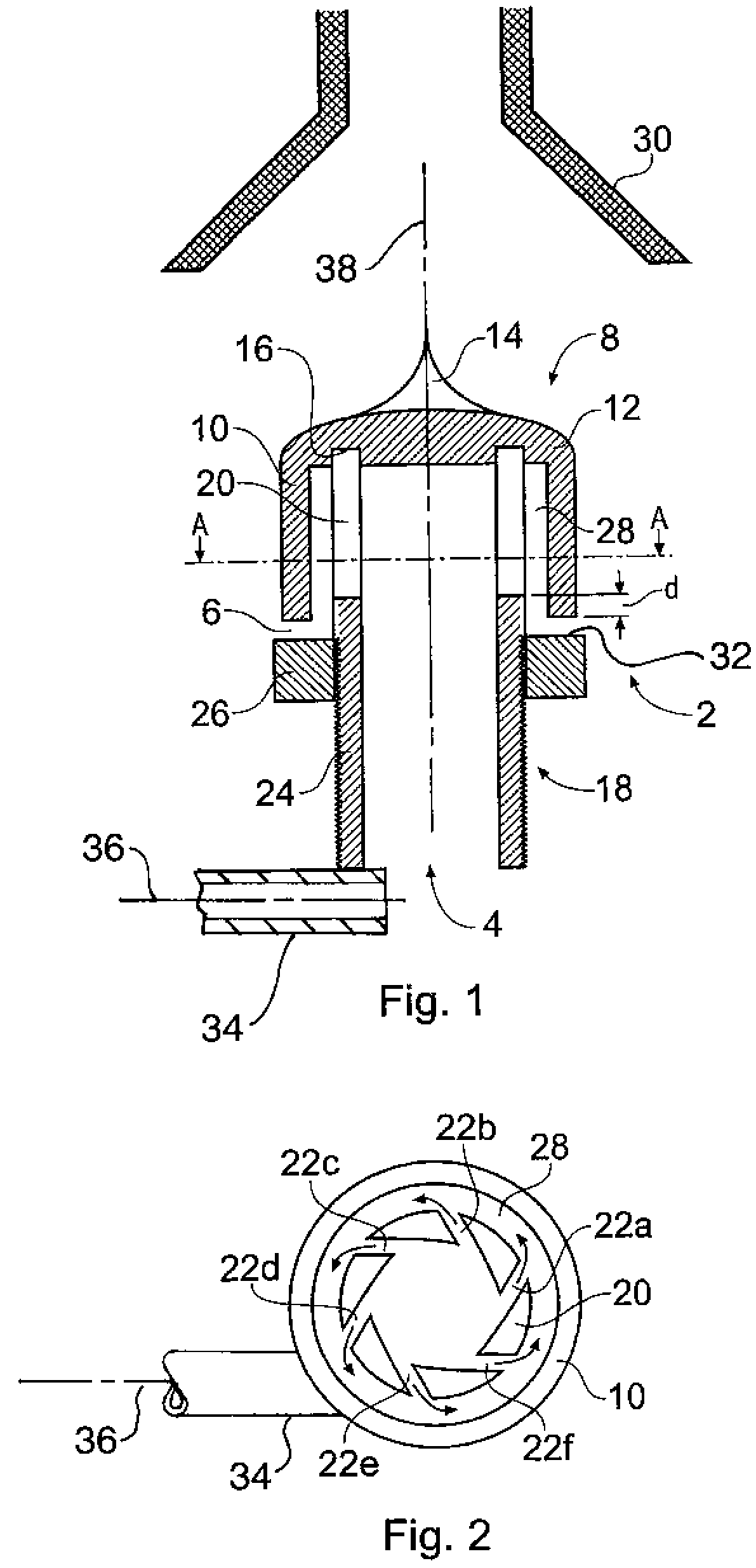
[0022]FIGS. 1 and 2 illustrate a fluidising apparatus comprising a flow chamber 2 having a fluid inlet 4 and a fluid outlet 6. The flow chamber 2 comprises a housing in the form of a cap 8 having a side wall 10 and a top 12 which in the region 14 is generally in the shape of a cone with a concave side wall. The underside of the top 12 is provided with an annular recess 16 in which is located a cylindrical flow guide 18. As best shown in FIG. 2, the upper portion 20 of the flow guide 18 is provided with a series of tangential slots 22a to 22f. The lower portion 24 of the flow guide 18 has an external thread which cooperates with an internal thread formed in an annular flange 26.

[0023]A fluid outlet 6 is defined between the side wall 10 of the cap 8 and the end wall 32 of flange 26 and an annular flow passage 28 is defined between the side wall 10 of the cap 8 and the upper portion 20 of the flow guide 18. The annular flow passage 28 is continuous with the fluid outlet 6, so that the ...


PUM


Abstract

According to the present invention there is provided fluidizing apparatus comprising: a flow chamber 2 having a fluid inlet 4 and a fluid outlet 6; means 18 for establishing a swirling flow in a fluid passing out of the fluid outlet; and a transport outlet 30 for transporting fluidized material away from the flow chamber 2, the transport outlet 30 being situated externally of the flow chamber 2.

Description

[0001]This invention relates to fluidising apparatus which can be used, for example, to fluidise settled solids, within a tank at atmospheric pressure or a pressure vessel at greater than atmospheric pressure in order to cause the solids to form a slurry which can be discharged from the tank or vessel.[0002]The slurry may pass into a slurry hydrotransport pipeline, designed to deliver the slurry at a required concentration over a required distance or static head with no moving parts subjected to abrasion or erosion. Alternatively, it may be fed directly into a slurry pump at a constant relative density or an inductor / jet pump, or other required processing system.BACKGROUND OF THE INVENTION[0003]U.S. Pat. Nos. 4,978,251, 4,952,099, 4,992,006 and 5,853,266, disclose fluidising units of the type comprising a supply duct which is arranged to be fed with liquid under pressure, and a discharge duct within the supply duct, and projecting beyond the outlet of the supply duct.[0004]A particu...

Claims


Application Information

Patent Timeline
Patent Type & Authority Patents(United States)
IPC IPC(8): B65G53/22B65G53/12B01J8/00B65G53/10
CPCB01J8/0025B65G53/22B65G53/12Y10T137/2087
Inventor DELVES, JAMES EDWARDYOUNG, NEIL KEITHDREW, DAVID OLIVER
Owner CAMERSON INT CORP
Why Eureka
Try Eureka