Shifting device and gear unit

a technology of shifting device and gear unit, which is applied in the direction of gearing control, gearing gearing, toothed gearing, etc., can solve the problems of many redundant gears, easy damage, and limited or no gear use, so as to reduce total weight, improve work efficiency, and improve work efficiency

Active Publication Date: 2014-01-14
PINION
View PDF14 Cites 8 Cited by
  • Summary
  • Abstract
  • Description
  • Claims
  • Application Information

AI Technical Summary

Benefits of technology

[0015]It is therefore an object of the present invention to provide an improved shifting device and an improved gear unit for a vehicle, in particular a vehicle that is driven by muscle force, which, in particular, is of more compact construction, permits a large number of gears and simultaneously a reduced total weight, and is simple to operate, as compared with the known shifting devices and gear units.

Problems solved by technology

Derailleurs of this kind provide up to 30 gears, although, by the nature of the system, many of the gears are redundant and some gears are of limited or no use due to high frictional losses caused by diagonal chain alignment.
The disadvantage with the derailleur principle is that, in addition to the large number of redundant gears and the frictional losses, the components are exposed and are therefore directly subject to environmental influences such as water and dirt and can very easily be damaged by impact.
The disadvantage with the principle of the hub gear in the rear axle is that the weight of the rotating masses is increased, and, in the case of bicycles with rear wheel suspension, that the unsprung mass relative to the total weight is increased.
Moreover, the center of gravity of the bicycle shifts in the direction of the rear axle, and this has a disadvantageous effect on the ride characteristics of the bicycle, especially in the case of mountain bikes with rear wheel suspension.
The disadvantage with this gear mechanism is that the construction of the overall gear mechanism is complex and is therefore, on the one hand, expensive to produce and, on the other hand, has a high weight due to the large number of components while providing only a small number of achievable gears.
One technical challenge with bicycle transmissions of this kind is to provide a compact construction combined with a large number of selectable gears.
The disadvantage with this system is the large axial extent of the design and the relatively small number of gears that can be obtained, namely 14.
The disadvantage with this gear unit is that a camshaft is moved axially to select the free gears and, as a result, the axial extent of the transmission design is great.
The disadvantage with this transmission is that the additional rotation is transmitted to the planetary mechanism by means of the selector shaft which is offset in parallel, thereby requiring a large amount of installation space for the gear unit.

Method used


Image

  • Shifting device and gear unit
  • Shifting device and gear unit
  • Shifting device and gear unit

Examples


Embodiment Construction

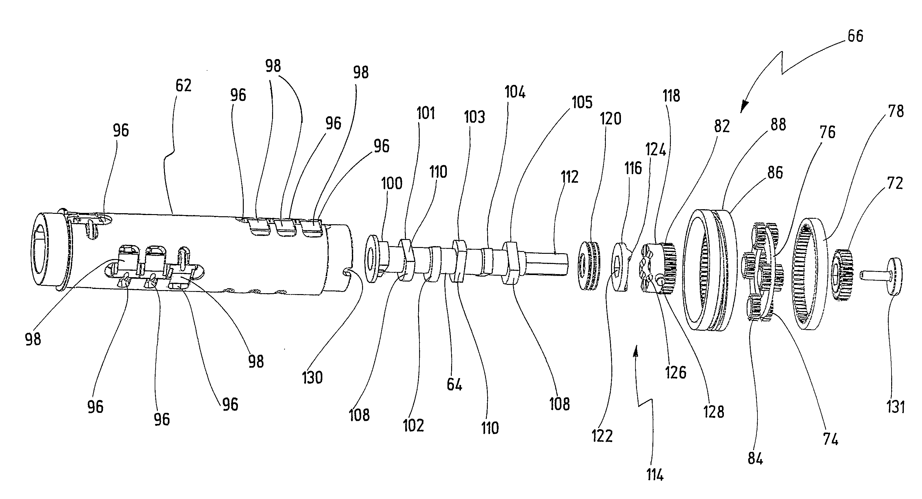
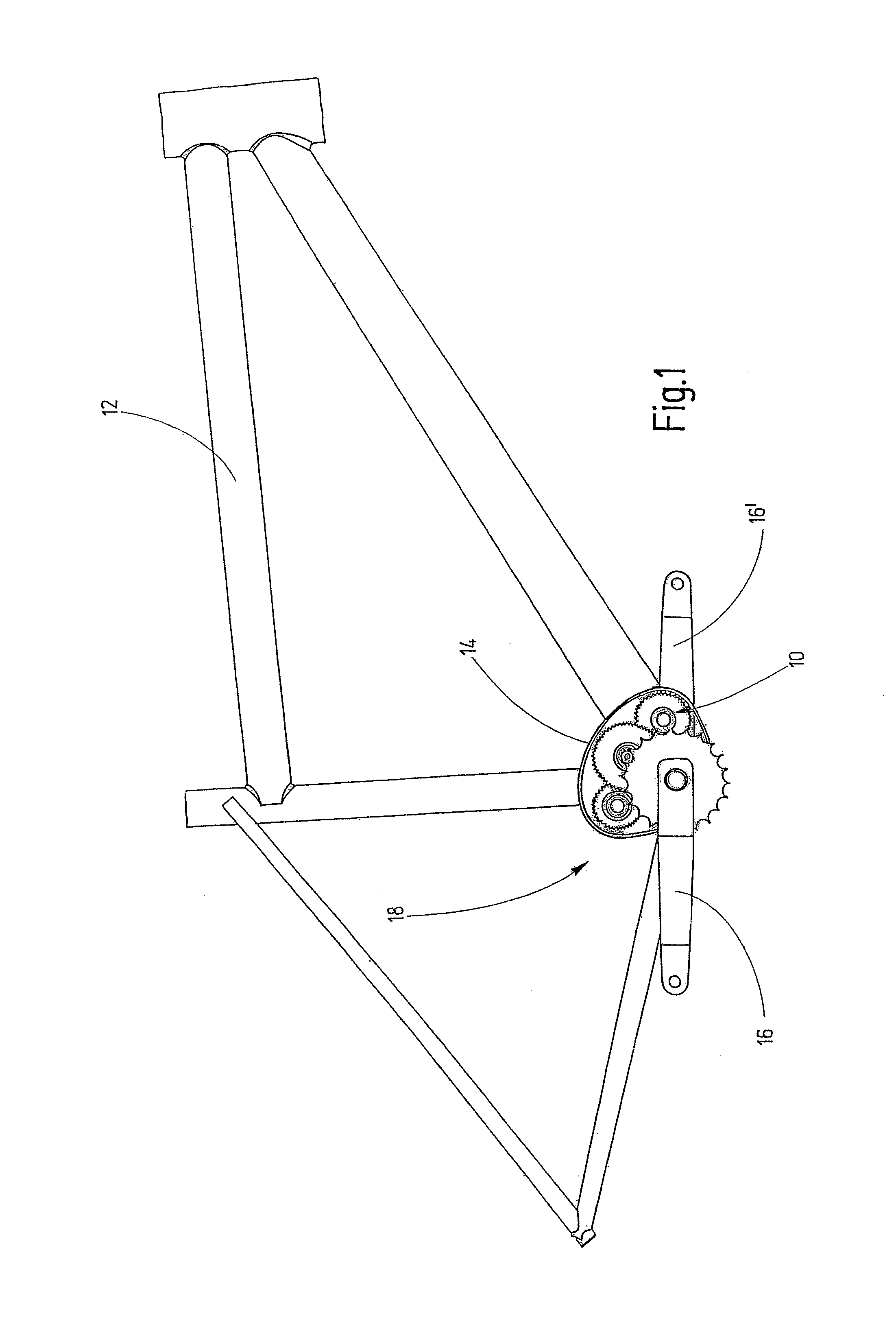
[0113]In FIG. 1, a gear unit is designated in general by 10.

[0114]FIG. 1 shows a side view of a bicycle frame 12, which has a gear case 14, in which the gear unit 10 is housed. In this illustration, the gear unit 10 is indicated only schematically and is designed as a compact unit, which is preferably arranged in a gear cage (not shown here). Here, the gear unit 10 is described by way of example for use with a bicycle but it can also be used on other vehicles operated by muscle force. Needless to say, the gear unit 10 can also be used for vehicles in which muscle force is used in combination with a power unit for driving the vehicle.

[0115]The gear unit 10 and the gear case 14 together with cranks 16 and 16′ form a multi-speed transmission 18.

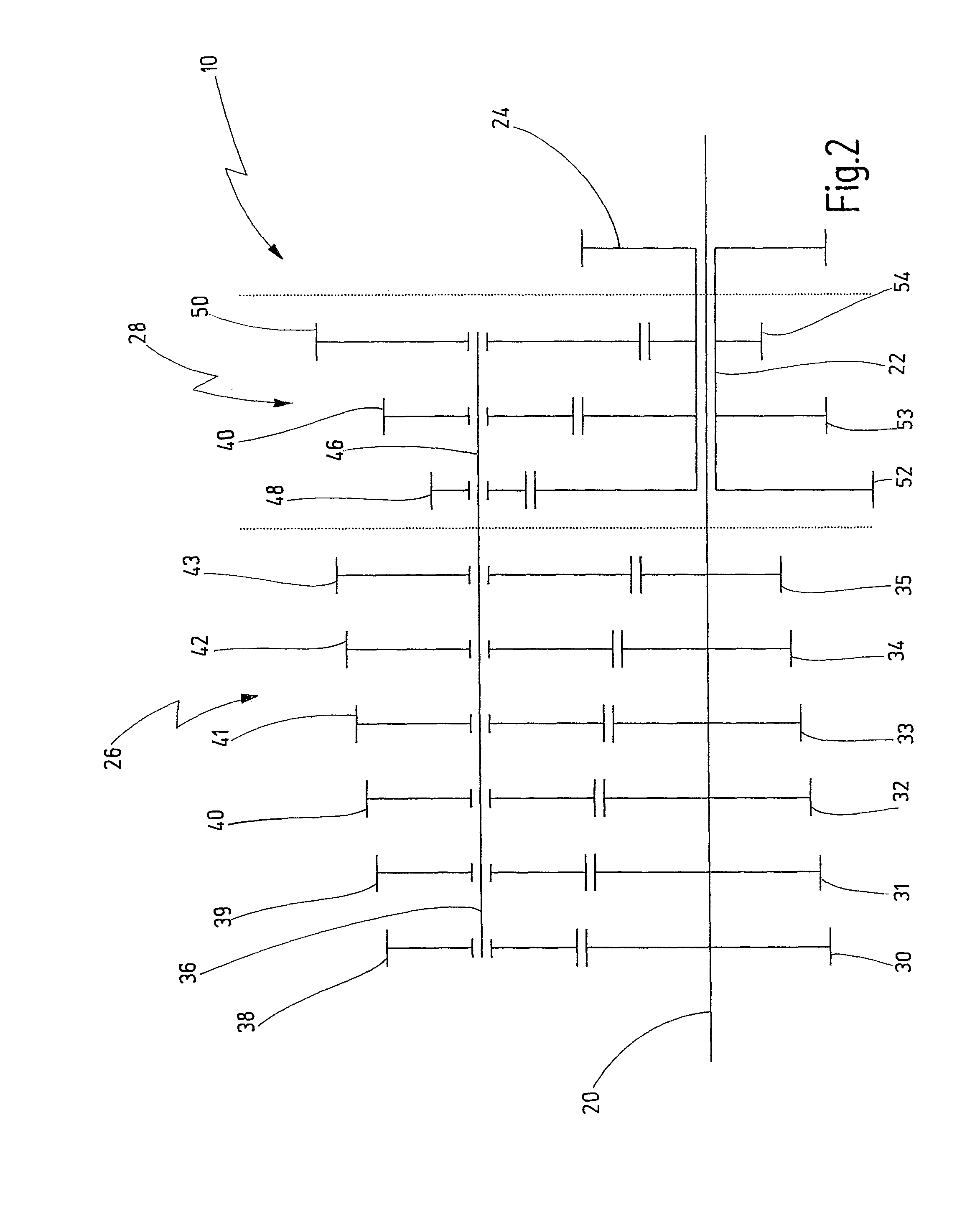
[0116]FIG. 2 shows a shift diagram of the gear unit 10.

[0117]The gear unit 10 has an input shaft 20 and an output shaft 22. The input shaft 20 is designed as a through shaft. The output shaft 22 is designed as a hollow shaft. The input shaft 20 ...


PUM


Abstract

The present invention relates to a shifting device for a transmission unit of a vehicle, in particular a vehicle that is driven by muscle force. The transmission unit has a first shaft, which is formed as a hollow shaft, on which a plurality of free gears is mounted. The free gears are in engagement with a corresponding plurality of gearwheels, which are mounted on a second shaft, wherein the free gears are connectable to the first shaft by means of selecting devices. The selecting devices can be actuated by means of a camshaft arranged coaxially in the first shaft, wherein the camshaft is connected to a driving device in order to be rotated relative to the first shaft to actuate the selecting means.

Description

CROSS-REFERENCE TO RELATED APPLICATIONS[0001]This is a Continuation application of International patent application PCT / EP 2010 / 069996, filed Dec. 16, 2010, which claims the priority of German patent application DE 10 2009 060 484.7, filed Dec. 18, 2009.BACKGROUND OF THE INVENTION[0002]The present invention relates to a shifting device for a transmission unit of a vehicle, in particular a vehicle that is driven by muscle force, having a first shaft, which is formed as a hollow shaft, on which a plurality of free gears is mounted, wherein the free gears are in engagement with a corresponding plurality of gearwheels, which are mounted on a second shaft, wherein the free gears are connectable to the first shaft by means of selecting means, wherein the selecting means can be actuated by means of a camshaft arranged coaxially in the first shaft, wherein the camshaft is connected to driving means in order to be rotated relative to the first shaft to actuate the selecting means.[0003]The p...

Claims


Application Information

Patent Timeline
Patent Type & Authority Patents(United States)
IPC IPC(8): F16H59/00F16H3/44F16H37/06
CPCF16H3/08F16H37/04B62M11/06B62M11/04F16H3/083B62M11/145Y10T74/19233Y10T74/19279
Inventor SCHMITZ, MICHAELLERMEN, CHRISTOPH
Owner PINION
Why Eureka
Try Eureka