Seat belt retractor and pretensioner combination

a technology of safety belts and pretensioners, which is applied in the direction of belt retractors, vehicle safety belts, vehicle components, etc., can solve the problems of corresponding space requirements, inability to mount the belt retraction and pretensioner combination, and high cost of continuous bending of tubes to spiral shapes of channels, etc., to achieve simple and cost-effective assembly

Active Publication Date: 2010-06-15
AUTOLIV DEV AB
View PDF12 Cites 5 Cited by
  • Summary
  • Abstract
  • Description
  • Claims
  • Application Information

AI Technical Summary

Benefits of technology

[0009]The basic concept of the present invention provides a arranged with at least one straight section in a parallel direction to the belt spool, between opposing housing sides of the U-shaped belt retractor housing and extends with an end section running in the plane of the drivewheel in a tangential direction to the drivewheel. The invention has the advantage that, because of the displacement of the tube from the outside of the one housing arm into the space between the two housing arms, the space requirement for this arrangement of the pretensioner is significantly reduced resulting in a more compact construction of the belt retractor and pretensioner combination. In this case, it is particularly advantageous that the tube is arranged within the dimensions of the belt retractor housing and inside the outside contour, so that no parts of the pretensioner unit still project over the contour of the belt roller housing. The tube itself with the essentially straight sections is simpler to produce and to mount, and finally, it is also possible to arrange the receptacle in the plane of the drivewheel because this plane is free of other built-in components of the tube with the exception of the end section that runs tangentially.
[0014]In an alternative embodiment, it can be provided that the tubular end section running in a tangential direction to the drivewheel includes a deformation introduced into the wall of the end section. The deformation is configured with such a radius that the mass bodies that are driven through the end section and run across the wall of the end section via the deformation are fed into the recesses of the drivewheel. This has the advantage that a particular component for driving the mass bodies into the drivewheel can be dispensed with and a simple and cost-effective assembly of the rotating pretensioner results.

Problems solved by technology

The known rotating pretensioner has the disadvantage that the arrangement of the tube with the channel for accepting mass spheres causes a corresponding space requirement on one side of the belt roller housing, particularly since the arrangement of tube surrounding the drivewheel clearly exceeds the dimensions of the belt roller housing.
It is therefore not possible to mount the belt retractor and pretensioner combination in every position in a motor vehicle.
Moreover, the one-sided arrangement of the tube also causes a non-uniform weight distribution, potentially causing assembly problems.
The continuous bending of the tube to the spiral shape of the channel is expensive to produce and difficult to mount on the belt roller housing.

Method used


Image

  • Seat belt retractor and pretensioner combination
  • Seat belt retractor and pretensioner combination
  • Seat belt retractor and pretensioner combination

Examples


Embodiment Construction

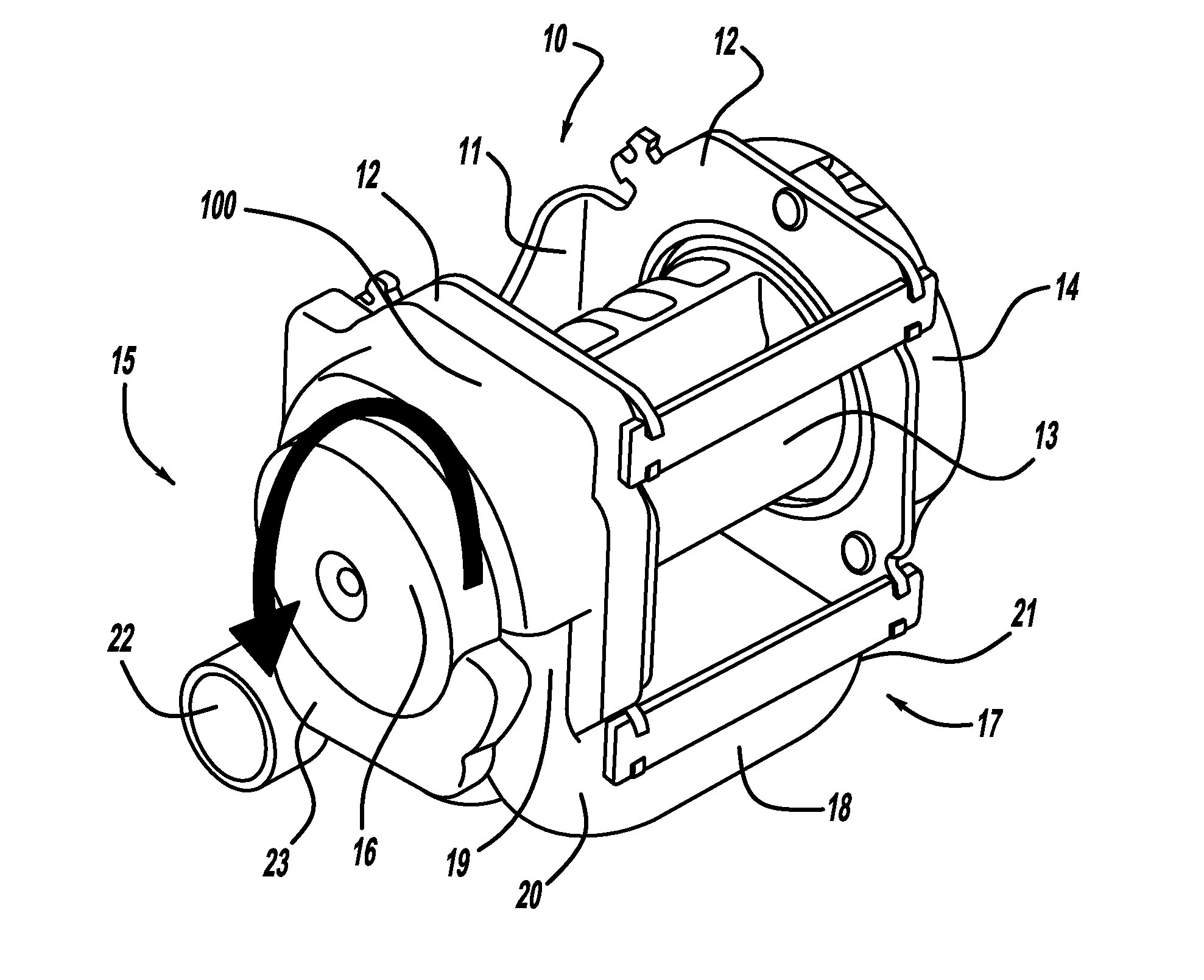
[0020]The belt retractor 10 and pretensioner unit depicted in FIG. 1 includes a U-shaped belt retractor housing 11 and opposing housing sides 12, whereby the belt spool 13 is mounted in the housing arms 12. A sensing unit 14, which can comprise a seatbelt-sensitive and / or vehicle-sensitive locking unit for the belt shaft and the associated take-up spring, is arranged on the outside of the associated housing side 12 on one end of a belt spool 13 on the right end in the illustration of FIG. 1.

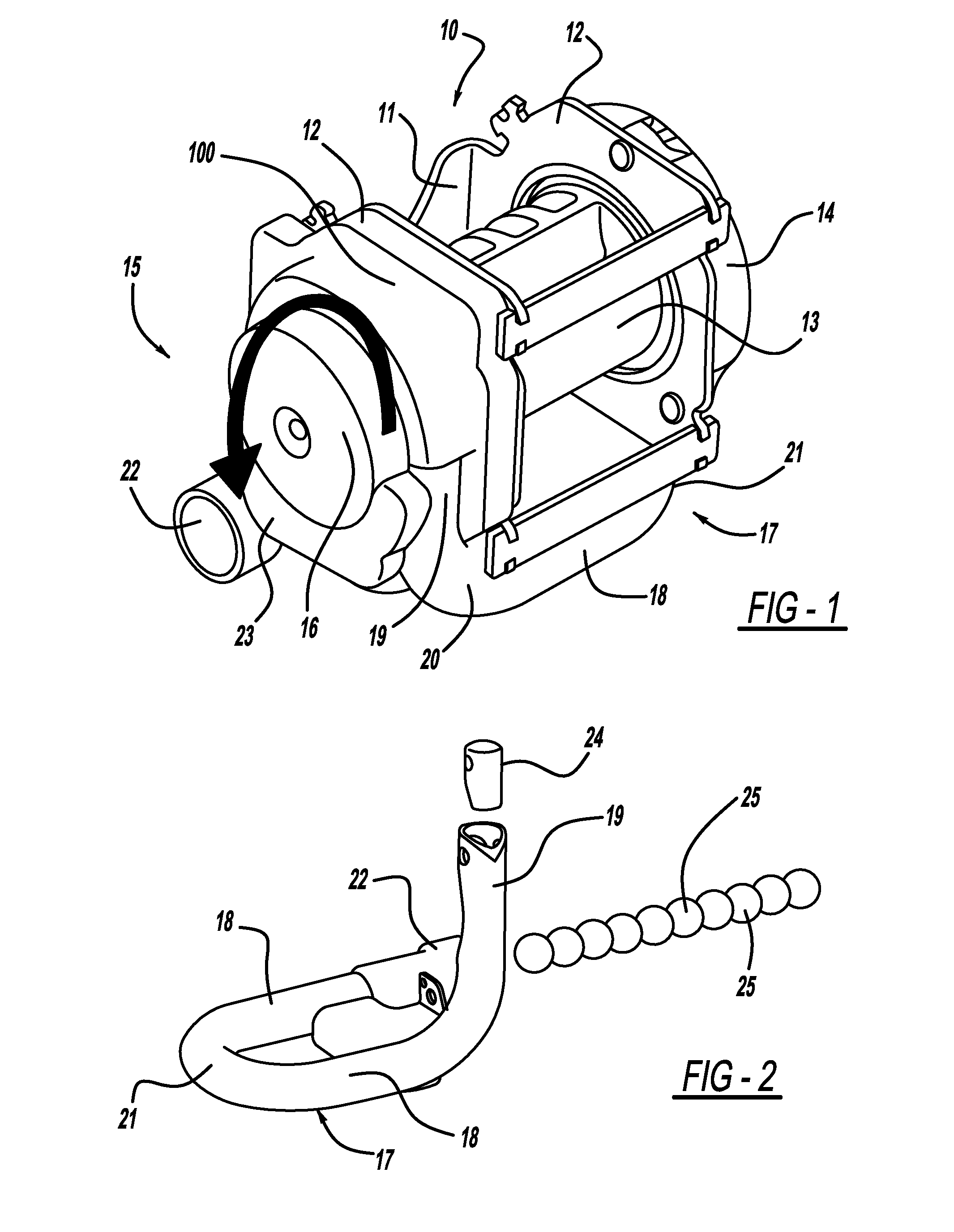
[0021]The drive side 15 of the associated retractor unit 10, includes a drivewheel 16 coupled to the projecting end of the belt spool 13 through the associated housing side 12 and is located opposite the sensing unit 14. The configuration and function of the drivewheel in cooperation with mass spheres 25 (see FIG. 2) serve as a drive means for pretensioning the seat belt, and is thoroughly presented in U.S. Pat. No. 5,881,962, which is herein incorporated by reference.

[0022]The mass spheres 25 ar...


PUM


Abstract

The invention relates to a seat belt retractor including a pretensioner especially for use in motor vehicles. The seat belt retractor includes a spool belt which supports belt webbing of the seat belt and rotates in the take-up direction of the safety belt when the pretensioning drive coupled to the belt spool is activated. The belt spool is associated with a drivewheel with recesses on the periphery thereof for accepting mass bodies acting as drive means for pretensioning the seat belt. The mass bodies are stored in a tube, which tangentially flows into the drivewheel, and the mass bodies are accelerated in the tube by means of a gas generator arranged at one end of the tube.

Description

CROSS REFERENCE TO RELATED APPLICATIONS[0001]This application claims priority to PCT / EP2004 / 013562, filed Nov. 30, 2004 and to DE 103 56 206.0 filed Dec. 2, 2003.BACKGROUND[0002]1. Field of the Invention[0003]The invention relates to a rotating retractor and pretensioner for a safety belt, especially in motor vehicles. The invention includes a belt retractor, the belt shaft of which supports the belt winding and rotates in the take-up direction of the safety belt when the tensioning drive coupled to the belt shaft is released. The belt shaft is associated with a drivewheel with recesses on the periphery thereof for accepting mass bodies acting as drive means, and the mass bodies are stored in a tube, which tangentially flows into the drivewheel, and the mass bodies are accelerated in the tube by means of a gas generator arranged at one end of the tube.[0004]2. Description of Related Art[0005]A rotating retractor and pretensioner having the above features is described in U.S. Pat. No...

Claims


Application Information

Patent Timeline
Patent Type & Authority Patents(United States)
IPC IPC(8): B60R22/34B60R22/46
CPCB60R22/4628B60R2022/4642B60R22/46B60R22/34
Inventor SCHMIDT, MARTINBOSCH, STEFANSCHNEIDER, THOMASSUHR, STEFANFREY, ERNE
Owner AUTOLIV DEV AB
Why Eureka
Try Eureka