Device for Fine Machining of Optically Effective Surfaces on In Particular Spectacle Lenses and Flexible Production Cell Comprising Such a Device

a technology of optically effective surfaces and flexible production cells, which is applied in the direction of grinding drives, grinding feeders, manufacturing tools, etc., can solve the problems of unsatisfactory access to the polishing machine, the relative large footprint area, and the inability to exchange workpieces and tools, so as to achieve very economic construction

Inactive Publication Date: 2015-02-05
SATISLOH AG
View PDF9 Cites 6 Cited by
  • Summary
  • Abstract
  • Description
  • Claims
  • Application Information

AI Technical Summary

Benefits of technology

[0021]If the afore-described device is used as an individual machine, i.e. not in a machine compound, then it obviously has to have a device for man/machine communication and a suitable control, for example a PC-based CNC control, which controls the drive modules and axial drives thereof. According to a further aspect of the invention a flexible production cell for the preliminary-processing and finish-processing of spectacle lenses accordingly comprises: (1) a device for the preliminary-processing of the optically effective surfaces of the spectacle lenses by milling, turning and/or grinding, which has regulated or controlled drive axes for workpiece and/or tool, with respectively associated drive modules, and (2) a device for the finish-processing of the optically effective surfaces of the spectacle lenses by polishing, such as, for example, the above-described device, which has regula...

Problems solved by technology

Although the previously known polishing machine also has a very narrow construction, in depth direction it requires, due to the lengthy horizontal travel paths of the piston-cylinder arrangements perpendicularly to the axes of rotation of the workpiece spindles, a relatively large footprin...

Method used


Image

  • Device for Fine Machining of Optically Effective Surfaces on In Particular Spectacle Lenses and Flexible Production Cell Comprising Such a Device
  • Device for Fine Machining of Optically Effective Surfaces on In Particular Spectacle Lenses and Flexible Production Cell Comprising Such a Device
  • Device for Fine Machining of Optically Effective Surfaces on In Particular Spectacle Lenses and Flexible Production Cell Comprising Such a Device

Examples


Embodiment Construction

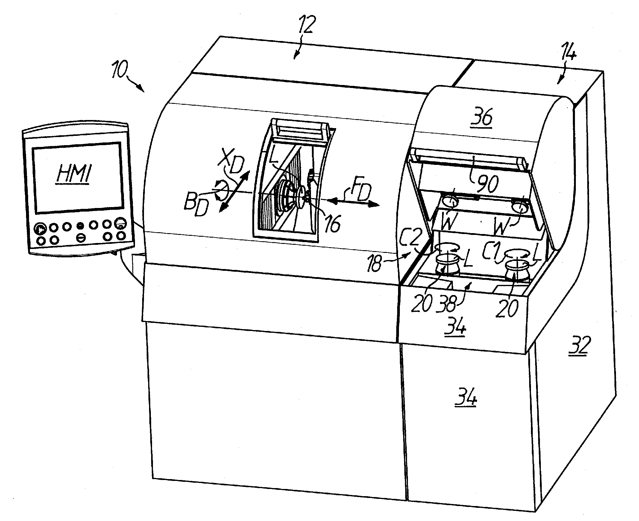
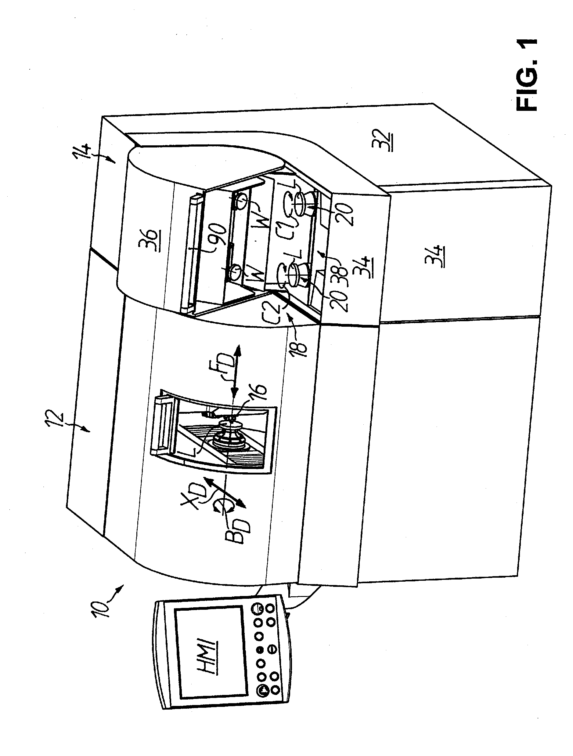
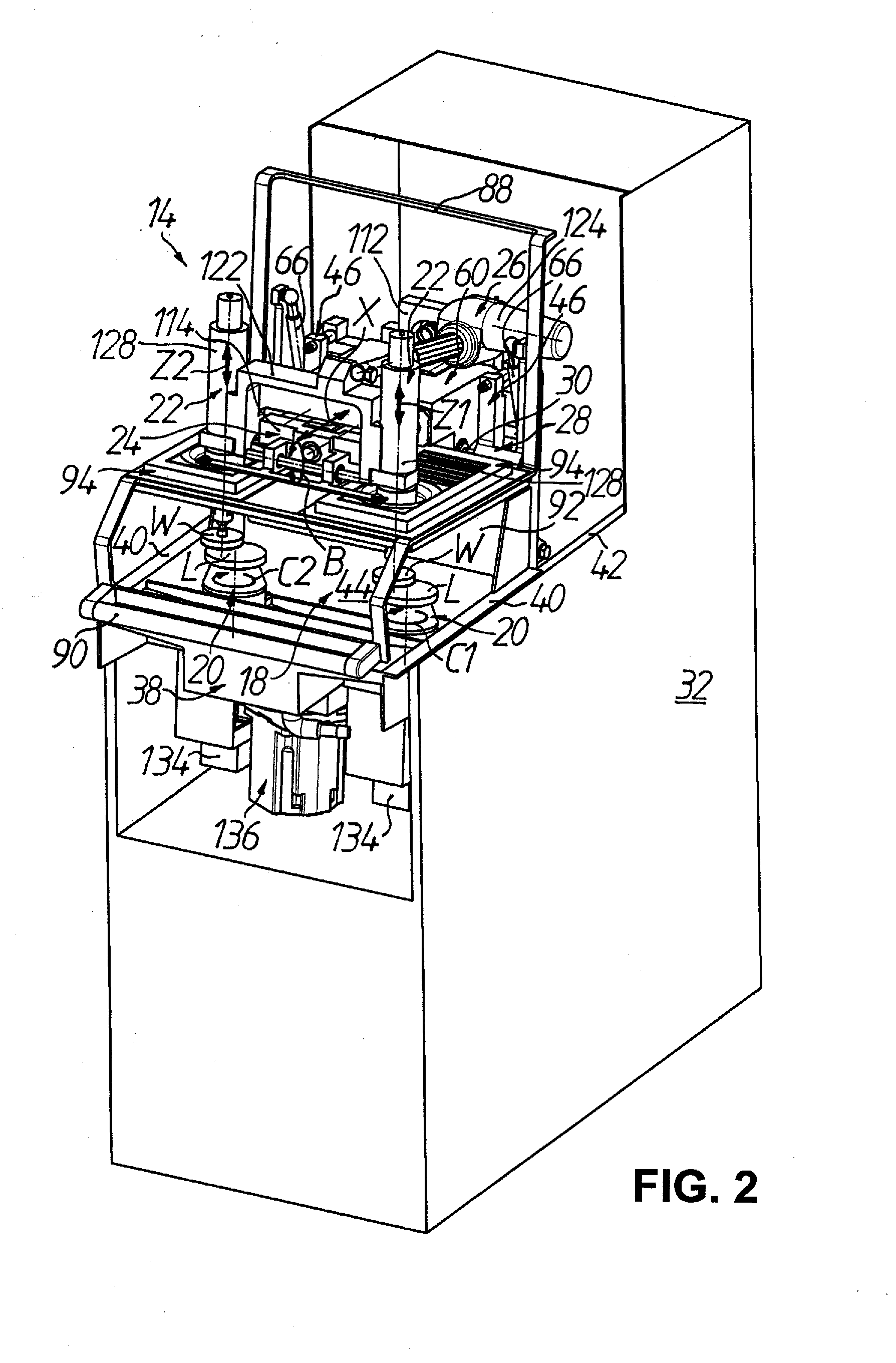
[0038]A flexible production cell for the preliminary-processing and finish-processing of spectacle lenses L in RX workshops is denoted generally by 10 in FIG. 1. In the illustrated embodiment the flexible production cell 10 comprises a device for preliminary-processing optically effective surfaces cc, cx (cf. FIGS. 10 and 11) of the spectacle lenses L, also called generator 12, as well as a device for processing the optically effective surfaces cc, cx of the spectacle lenses L to finished state in the form of a polishing machine 14, which is mechanically and electrically docked as a module to the generator 12, as later described in more detail. In the following, there shall be explained primarily the construction and functioning of the polishing machine 14 which in the illustrated embodiment is realized in “twin” mode of construction so that two spectacle lenses L can be polished simultaneously.

[0039]With regard to the generator 12 it may merely be mentioned at this point that this ...


PUM


Abstract

The invention relates to a polishing machine for spectacle lenses, including a least one workpiece spindle protruding into a workspace for a rotary drive of the spectacle lens about a workpiece rotational axis. At least one feed device lowers and raises a polishing tool relative to the spectacle lens. An oscillation drive unit moves the feed device back and forth in an oscillation direction, which during the polishing runs substantially transversely to the workpiece rotational axis. A swivel drive unit swivels the feed device about a swivel-adjusting axis which runs substantially perpendicular to the workpiece rotational axis and substantially normal to the oscillation direction. A swivel mechanism is provided to swivel the feed device, the oscillation drive unit and the swivel drive unit relative to the workpiece.

Description

TECHNICAL FIELD[0001]The present invention relates generally to a device for the finish-processing of optically effective surfaces in accordance with the preamble portion of claim 1. In particular, the invention relates to a device for finish-processing of the optically effective surfaces of spectacle lenses such as used in so-called “RX workshops”, i.e. production facilities for producing individual spectacle lenses according to the prescription on a large scale. Moreover, the invention relates to a flexible production cell for the processing of spectacle lenses, which comprises such a finish-processing device.PRIOR ART[0002]The processing of the optically effect surfaces of spectacle lenses by machining can be roughly divided into two processing phases, namely initially preliminary-processing of the optically effective surface for producing the macro-geometry according to prescription and then processing of the optically effective surface to finished state in order to eliminate pr...

Claims


Application Information

Patent Timeline
IPC IPC(8): B24B47/22B24B13/00
CPCB24B13/0037B24B47/22B24B13/00B24B27/0084B24B41/005
Inventor WALLENDORF, STEFFENSCHAFER, HOLGER
Owner SATISLOH AG
Why Eureka
Try Eureka