Beverage frothing device and jug comprising said device

a technology of frothing device and beverage, which is applied in beverage vessels, domestic applications, kitchen equipment, etc., can solve the problems of clogging of air inlet ports, unfrothed milk generation, and known devices not providing the same flexibility of use as other frothing devices, so as to prevent the flow of frothed beverage, facilitate assembly, and compact construction of frothing devices

Active Publication Date: 2016-10-13
VERSUNI HLDG BV
View PDF1 Cites 6 Cited by
  • Summary
  • Abstract
  • Description
  • Claims
  • Application Information

AI Technical Summary

Benefits of technology

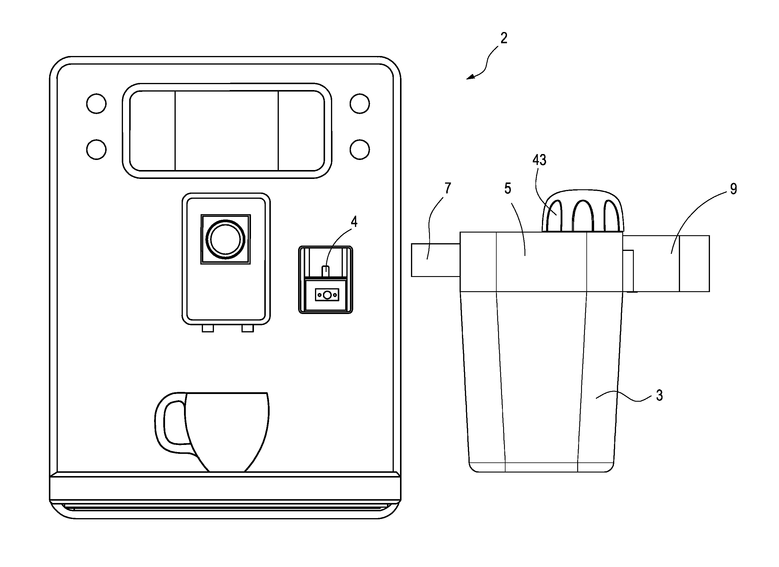
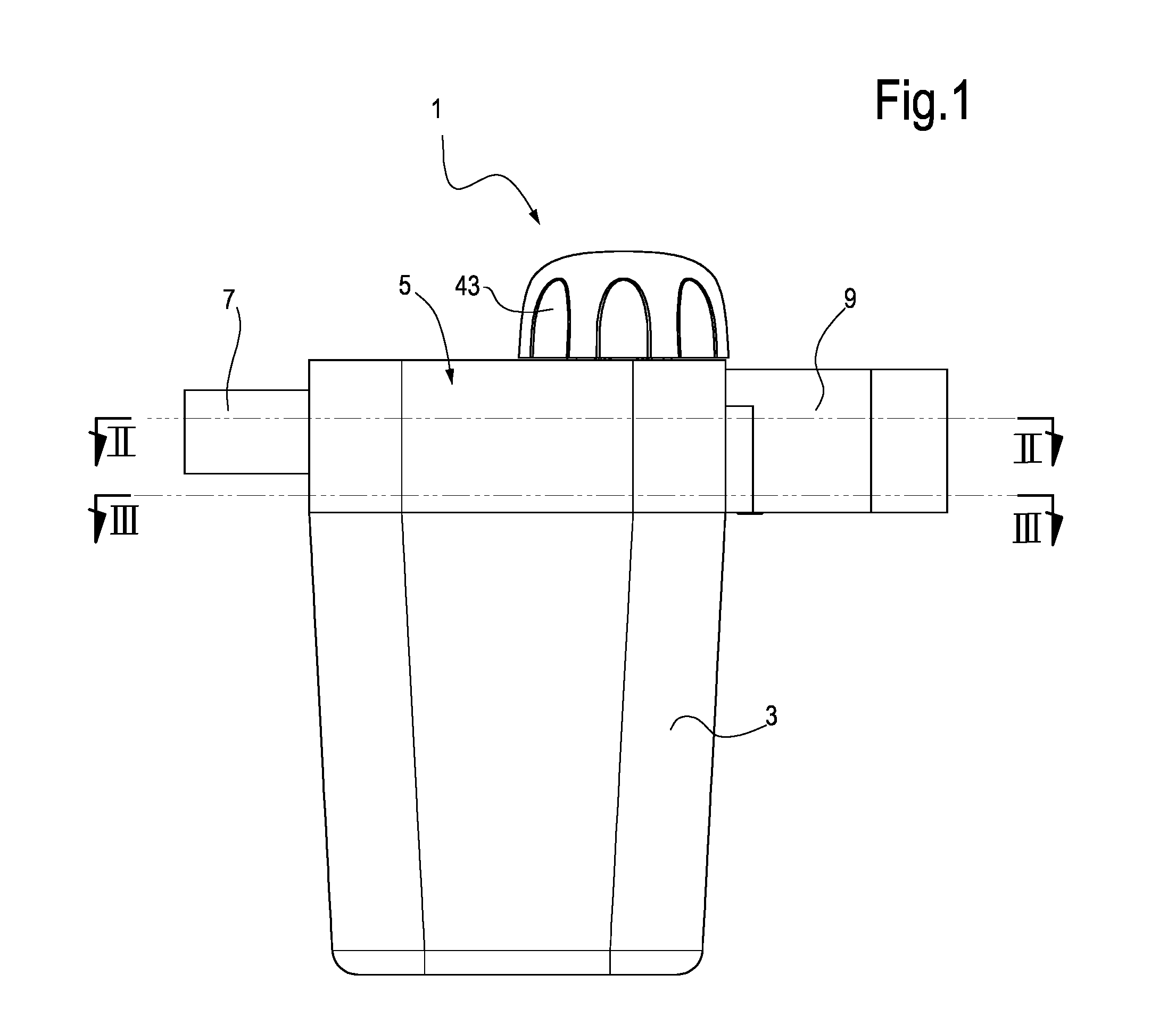
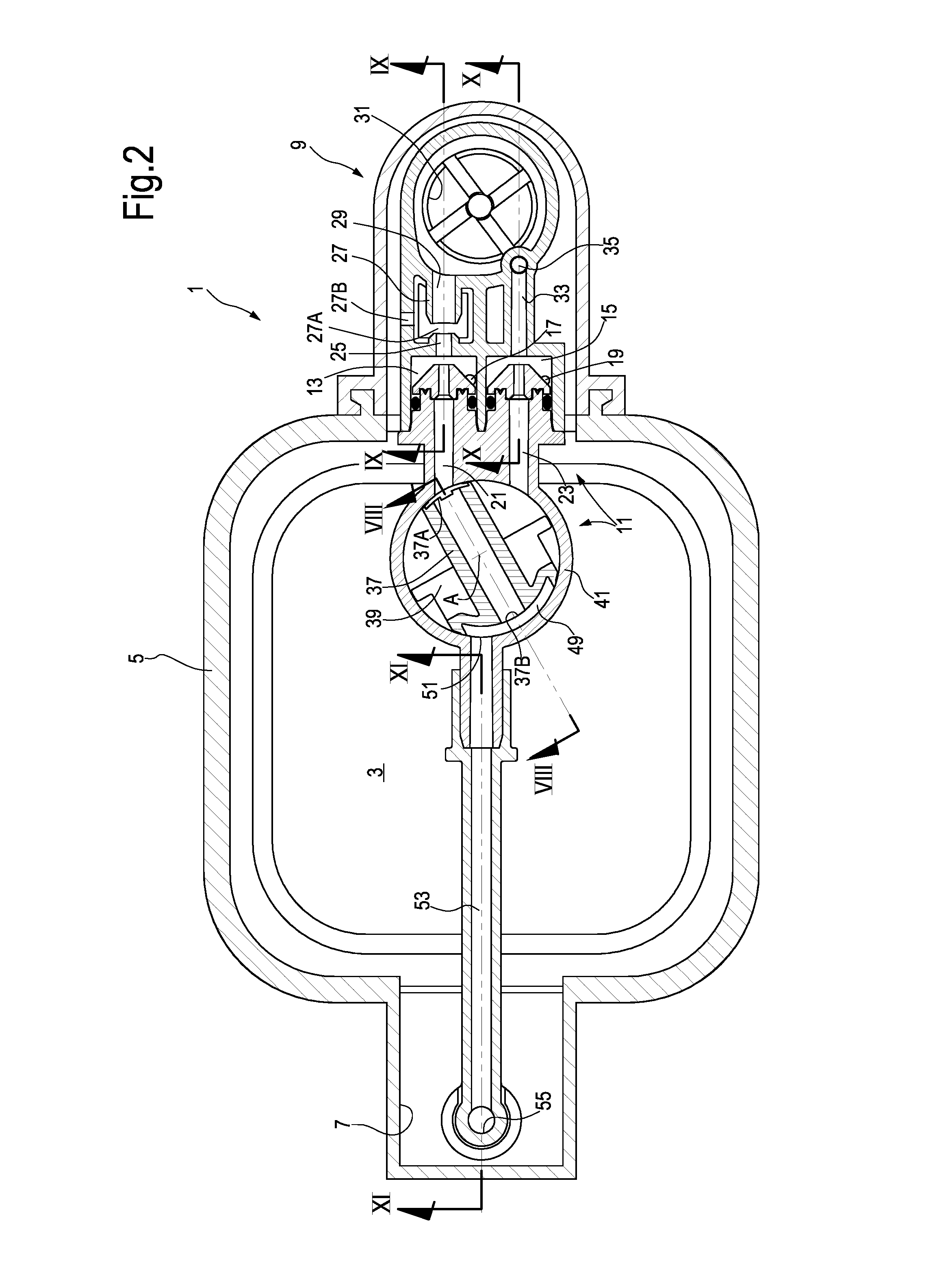
[0011]According to preferred embodiments, the second beverage passageway comprises a second beverage dispensing spout, wherefrom unfrothed milk is dispensed. The first beverage dispensing spout and the second beverage dispensing spout can be designed so that when frothed beverage is produced, the frothed beverage is prevented from entering in the second beverage dispensing spout, due e.g. to cyclone effect provided by the first beverage dispensing spout. For example the outlet aperture of the second beverage dispensing spout can be protected by a partition wall or any other suitable arrangement, preventing the frothed beverage flow, which is dispensed though the first beverage dispensing spout, from entering the second beverage dispensing spout. In some embodiments the first beverage dispensing spout and the second beverage dispensing spout can be arranged side by side, with both outlet apertures thereof oriented downwardly.
[0012]According to some embodiments, the steam delivery nozzle can be arranged on a displaceable switching member, such that the steam delivery nozzle can be moved selectively in the various positions thereof by moving the switching member in corresponding switching positions. The switching member can be rotatable about a rotation axis to take one of the various selective switching positions. According to other embodiments, the switching member can be movable according to a translation rather than rotation movement. For instance, the switching member can be arranged on or formed by a slide. A rotary switching member is however preferred, as it results in a more compact construction of the frothing device. Additionally, a rotary switching member is easier to assemble and more reliable and robust. In some embodiments, the axis of rotation of the switching member is orthogonal to the steam delivery nozzle. In some embodiments, the switching member can comprise two or more steam delivery nozzles, which are selectively placed in fluid communication with a steam source and with either one, the other or both steam inlet ducts.

Problems solved by technology

If the air inlet port is entirely closed by the pin, no air is sucked into the milk path and hot, unfrothed milk is generated.
Milk frothing devices of this kind are efficient and flexible in use but suffer from same disadvantages mainly caused by the narrow cross section of the air inlet port.
This causes often the risk of clogging of the air inlet port, for example due to milk entering the air inlet port.
However, this known device does not provide the same flexibility of use of other frothing devices, which are provided with an air adjusting pin.
The lack of an air adjusting pin makes the device unsuitable for the production of hot, unfrothed milk.

Method used


Image

  • Beverage frothing device and jug comprising said device
  • Beverage frothing device and jug comprising said device
  • Beverage frothing device and jug comprising said device

Examples


Embodiment Construction

[0037]The following detailed description of exemplary embodiments refers to the accompanying drawings. The same reference numbers in different drawings identify the same or similar elements. Additionally, the drawings are not necessarily drawn to scale. Also, the following detailed description does not limit the invention. Instead, the scope of the invention is defined by the appended claims.

[0038]Reference throughout the specification to “one embodiment” or “an embodiment” or “some embodiments” means that the particular feature, structure or characteristic described in connection with an embodiment is included in at least one embodiment of the subject matter disclosed. Thus, the appearance of the phrase “in one embodiment” or “in an embodiment” or “in some embodiments” in various places throughout the specification is not necessarily referring to the same embodiment(s). Further, the particular features, structures or characteristics may be combined in any suitable manner in one or ...


PUM


Abstract

The beverage frothing device comprises a first beverage passageway comprised of: a first beverage suction chamber (13) in communication with a first beverage suction duct (17) and a first steam inlet duct (21), wherein the first beverage suction duct is configured for communication with a beverage container; an air inlet port (27A); a frothing arrangement for mixing beverage delivered through the first beverage suction duct (17) with air from the air inlet port (27A) and producing frothed beverage; a first beverage dispensing spout (31), wherefrom frothed beverage is dispensed. The beverage frothing device further comprises a second beverage passageway comprised of a second beverage suction chamber (15) in communication with a second beverage suction duct (19) and a second steam inlet duct (23), wherein the second beverage suction duct is configured for communication with the beverage container. A steam feeding arrangement is further provided, which is configured for dispensing steam selectively to the first steam delivery duct (21), for producing frothed beverage, or to the second steam delivery duct (23) for producing hot, unfrothed beverage.

Description

FIELD OF THE INVENTION[0001]The invention relates to beverage-producing devices and accessories. More specifically, the invention relates to improvements concerning beverage frothing devices, in particular milk frothing devices and jugs provided with milk frothing devices. The invention further relates to beverage-producing machines including frothing devices.BACKGROUND OF THE INVENTION[0002]Beverage-producing machines, for example coffee and espresso producing machines, are often provided with a device for the production of frothed milk or hot milk. A milk frothing device usually comprises a milk suction chamber wherein a steam delivery nozzle delivers a flow of pressurized steam generated by a steam generator in the beverage-producing machine. A milk suction duct is in fluid communication with a milk container and with the milk suction chamber. A flow of hot, pressurized steam flowing through the milk suction chamber generates, by Venturi effect, a negative pressure in the milk su...

Claims


Application Information

Patent Timeline
Patent Type & Authority Applications(United States)
IPC IPC(8): A47J31/44A47J31/60
CPCA47J31/4485A47J31/60A47J31/4489
Inventor FERRARO, ANDREASANTINI, MARCO
Owner VERSUNI HLDG BV
Why Eureka
Try Eureka