Releasing device

a technology of releasing device and trigger, which is applied in the direction of firing/triggering mechanism, weapon components, weapons, etc., can solve the problems of complicated shapes and high production costs, and achieve the effect of low trigger weigh

Active Publication Date: 2014-01-21
ATZL ANDREAS
View PDF15 Cites 9 Cited by
  • Summary
  • Abstract
  • Description
  • Claims
  • Application Information

AI Technical Summary

Benefits of technology

[0010]Usually, the pressure of the striker spring contacting the firing pin or the firing-pin piece in the series provided according to the invention for roller bodies contacting each other is derived via the control body. Among other things, through the friction prevailing between the roller bodies, the force that is provided by the tensioned striker spring and usually lies in the range of 100 to 110 Newton, that is, 10 to 11 kg, can be reduced to a very low trigger weight. In preferred embodiments, it is possible to achieve trigger weights of 1 Newton or 100 grams and below with releasing devices constructed according to the invention. One special advantage of the releasing device according to the invention, however, is also the quickness with which the motion released by the release trigger can be transferred via the series of roller bodies and thus via the transmission mechanism constructed according to the invention to the control body and thus to the firing pin or the firing-pin piece. Despite these advantages, releasing devices according to the invention can be produced more easily due to their simpler structure and thus also more economically than the lever-transmission mechanisms known in the prior art. Another advantage of the invention lies in that releasing devices according to the invention could also be realized with very small spatial requirements, that is, can be realized in a small structural size.
[0011]For the sake of completeness, it is noted that the releasing devices according to the invention could be combined with very many different bolt actions for firearms known in the prior art. The control body could here act directly or also indirectly by via the intermediate connection of additional parts on the firing pin or the firing-pin piece. Releasing devices according to the invention, however, do not necessarily have to be used in firearms. If a releasing device for a firing pin or a firing-pin piece is also needed at another position, then this could be constructed according to the invention.
[0012]Favorably it is provided that the roller bodies forming the series are arranged on behind the other and each roller body contacts exactly two adjacent roller bodies, apart from the first and last roller bodies of the series.
[0013]Especially preferred embodiments of the invention provide that every two successive and / or contacting roller bodies of the series of roller bodies are arranged offset relative to each other. In this sense, the roller bodies of the series should not lie one behind each other exactly in a line, but instead should be arranged offset somewhat relative to each other especially viewed in the direction of the series with respect to its centers or center axes. Furthermore, it is preferable in the sense of the invention if the series of roller bodies is arranged in a transmission channel defined by channel walls. The distance of opposing channel walls should here be at least somewhat greater than the diameter of the roller bodies. Preferably, however, the distance of opposing channel walls is less than twice the diameter of each roller body. In this way it can be guaranteed that the roller bodies are arranged one behind the other, in particular, despite their offset. Preferably it is further provided that each roller body contacts at least one of the channel walls.
[0014]Through the offset of the roller bodies relative to each other, however, through their contact on at least one channel wall, the forces of the striker spring introduced via the control body onto the series of roller bodies are reduced in an especially good way, so that, overall, a very low trigger weight can be realized for the releasing device according to the invention. Preferably, it is provided here that the balls do indeed contact each other, the channel walls, and the control body, but otherwise move freely, that is, they are not also further connected to each other. In particular, in order to maintain or to specify the offset of the roller bodies relative to each other, preferred embodiments of the invention are provided such that at least one of the channels walls has at least one wall section projecting in the direction toward the channel interior, advantageous a series of alternating wall sections projecting in the direction toward the channel interior and recessed in the opposite direction.
[0015]In order to be able to transfer the motion of the release trigger generated by the activation by hand or with one finger to the series of roller bodies, especially preferred embodiments of the invention provide that at least one sub-area of at least one of the channel walls is constructed as a rocker that can pivot about at least one rocker pivoting axis. Here a locking piece could be arranged on the release trigger, wherein the rocker can be fixed in a first position and can be released in at least one released position. The rocker can be reset, in particular, in a releasing device released by the pressure of the striker spring, in that the rocker is spring-loaded from at least one rocker pull-back spring that is advantageously adjustable in its spring force, advantageously outside of the rocker pivoting axis.

Problems solved by technology

These usually have very complicated shapes and are thus expensive to produce.

Method used


Image

  • Releasing device
  • Releasing device
  • Releasing device

Examples


Embodiment Construction

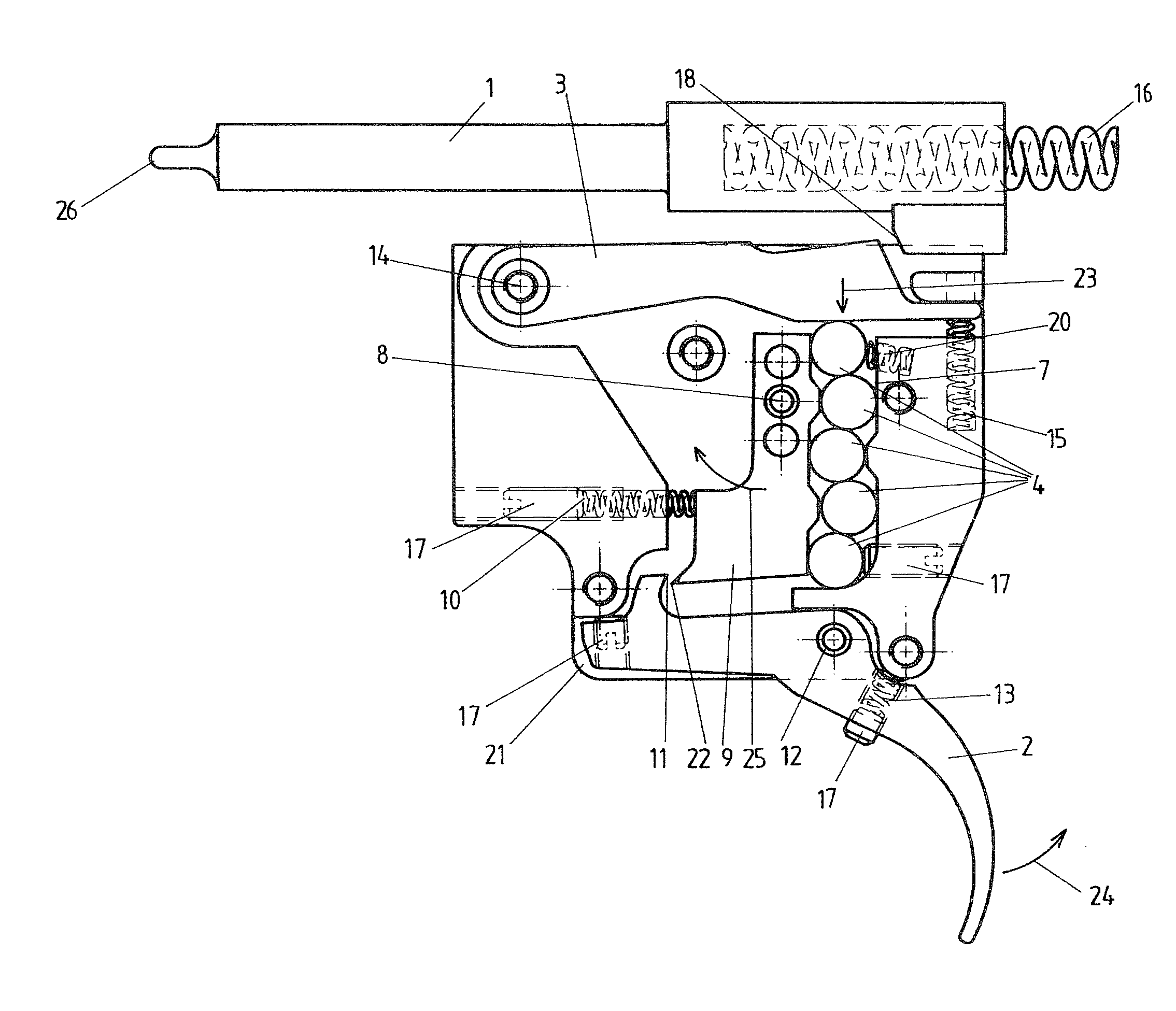
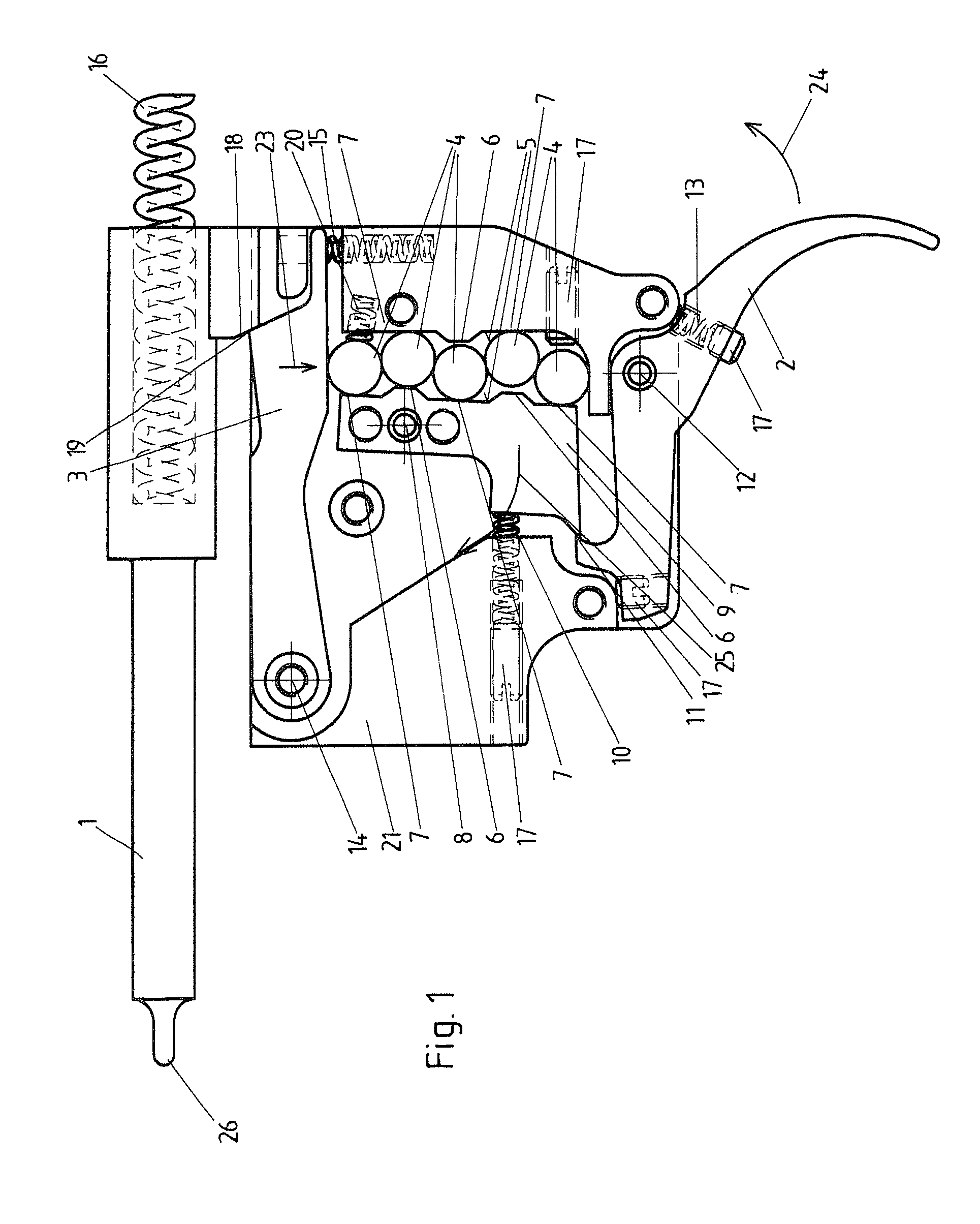
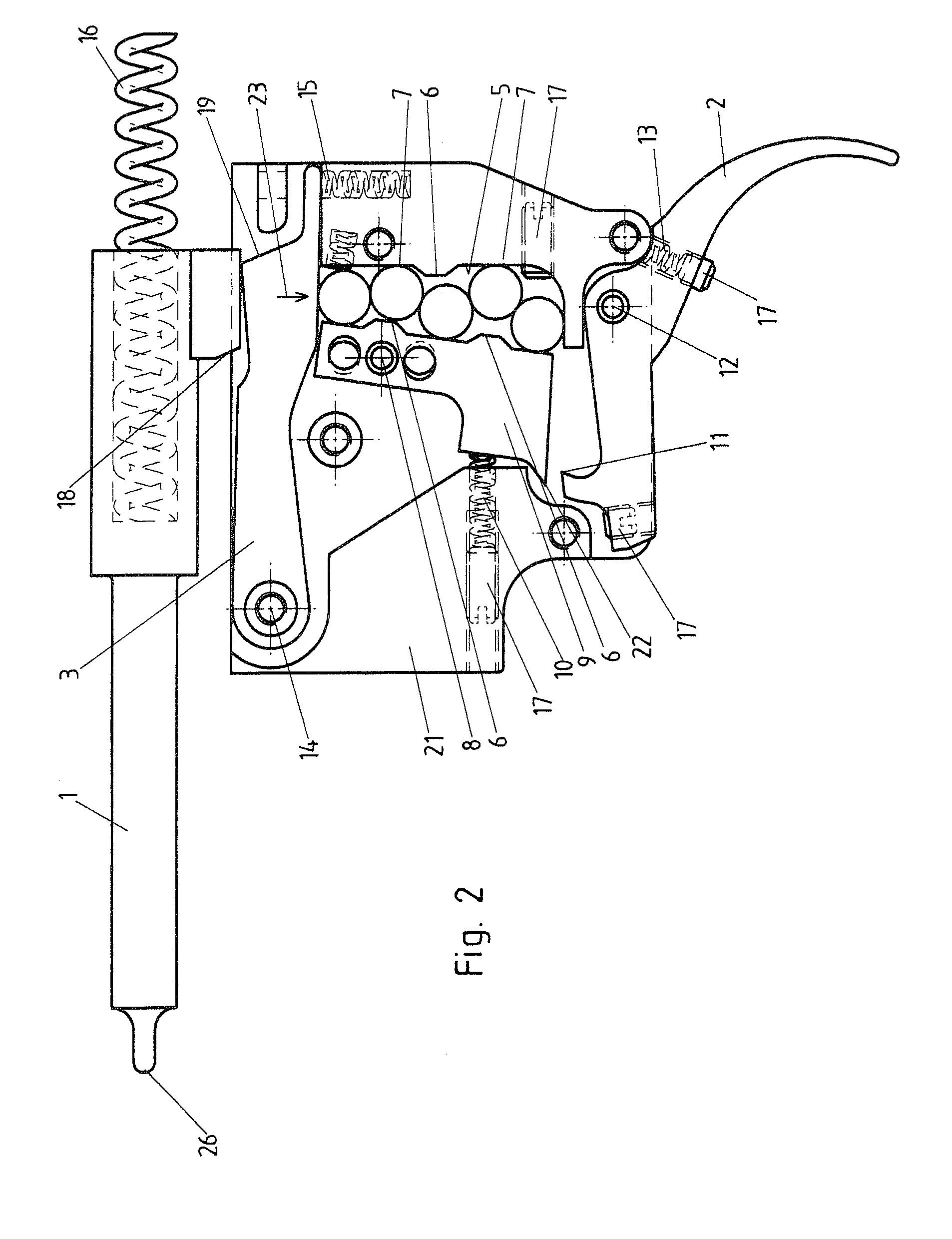
[0021]FIG. 1 shows the releasing device or the trigger of the first embodiment in a ready-to-fire position from which a shot can be released through activation of the release trigger 2 that is often also called a trigger blade. FIG. 2 shows the releasing device in the fired state in which the firing pin 1 is pushed by the striker spring 16 completely forward in the direction toward the cartridge not shown here. FIG. 3 shows the releasing device in a released state that is used for resetting the releasing device into the ready-to-fire position according to FIG. 1 as an intermediate step.

[0022]In the tensioned position according to FIG. 1, the striker spring 16 presses the firing pin 1 in the direction toward the cartridge not shown here, so that the firing pin 1 is biased accordingly. The bevel face 18 on the firing pin 1 is here supported on the bevel face 19 of the control body 3. Through the use of the bevel faces 18 and 19, the force of the striker spring 16 acting on the firing ...


PUM


Abstract

A releasing device for a spring-loaded firing pin (1) or a spring-loaded firing-pin piece, in particular of a firearm, with at least one release trigger (2) that can be activated by hand, in particular, with at least one finger, and with a control body (3) acting on the firing pin (1) or the firing-pin piece. A transmission mechanism is arranged and / or acts between the release trigger (2) and the control body (1), and the transmission mechanism has a series of roller bodies (4) lying one on the other, advantageously balls and / or cylinders.

Description

CROSS-REFERENCE TO RELATED APPLICATIONS[0001]This application claims the benefit of Austrian Patent Application No. A 1671 / 2009, filed Oct. 23, 2009, which is incorporated herein by reference as if fully set forth.BACKGROUND[0002]a) Field of the Invention[0003]The present invention relates to a releasing device for a spring-loaded firing pin or for a spring-loaded firing pin piece, in particular, of a firearm, with at least one release trigger that can be activated by hand, in particular, with at least one finger, and with a control body acting on the firing pin or on the firing-pin piece, wherein a transmission mechanism is arranged and / or acts between the release trigger and the control body.[0004]b) Description of Related Prior Art[0005]Releasing devices according to the class are used primarily for firearms. They are used to transmit a releasing movement triggered by hand, usually with one finger, so that the control body releases the firing pin or the firing-pin piece, so that ...

Claims


Application Information

Patent Timeline
Patent Type & Authority Patents(United States)
IPC IPC(8): F41A19/00
CPCF41A19/12F41A19/31F41A19/16F41A19/17F41A19/10
Inventor ATZL, ANDREAS
Owner ATZL ANDREAS
Why Eureka
Try Eureka