
Chip card holding mechanism and portable electronic device

a technology of holding mechanism and chip card, which is applied in the direction of coupling device connection, electrical apparatus casing/cabinet/drawer, instruments, etc., can solve the problems of inconvenient detachment and replacement of chip cards, complex structure of existing chip card holding mechanisms, and the inability of chip card holding mechanisms to unlock

Inactive Publication Date: 2014-01-21
FU TAI HUA IND SHENZHEN +1
View PDF2 Cites 10 Cited by
  • Summary
  • Abstract
  • Description
  • Claims
  • Application Information

AI Technical Summary

Benefits of technology

The present invention provides an improved chip card holding mechanism for portable electronic devices such as mobile phones and tablets. The chip card holding mechanism is convenient to detach and replace the chip card, with a simple structure. Moreover, it can unlock even at low pressure, thereby avoiding damage to the device while ensuring secure holding of the chip card.

Problems solved by technology

Thus, it is inconvenient to detach and replace the chip card.
In addition, the existing chip card holding mechanism has a complex structure.
The chip card holding mechanism may not unlock if the pressure applied is not strong enough to rotate the holding member.
On the other hand, too much pressure on the cover may cause damage.

Method used


Image

  • Chip card holding mechanism and portable electronic device
  • Chip card holding mechanism and portable electronic device
  • Chip card holding mechanism and portable electronic device

Examples


Embodiment Construction

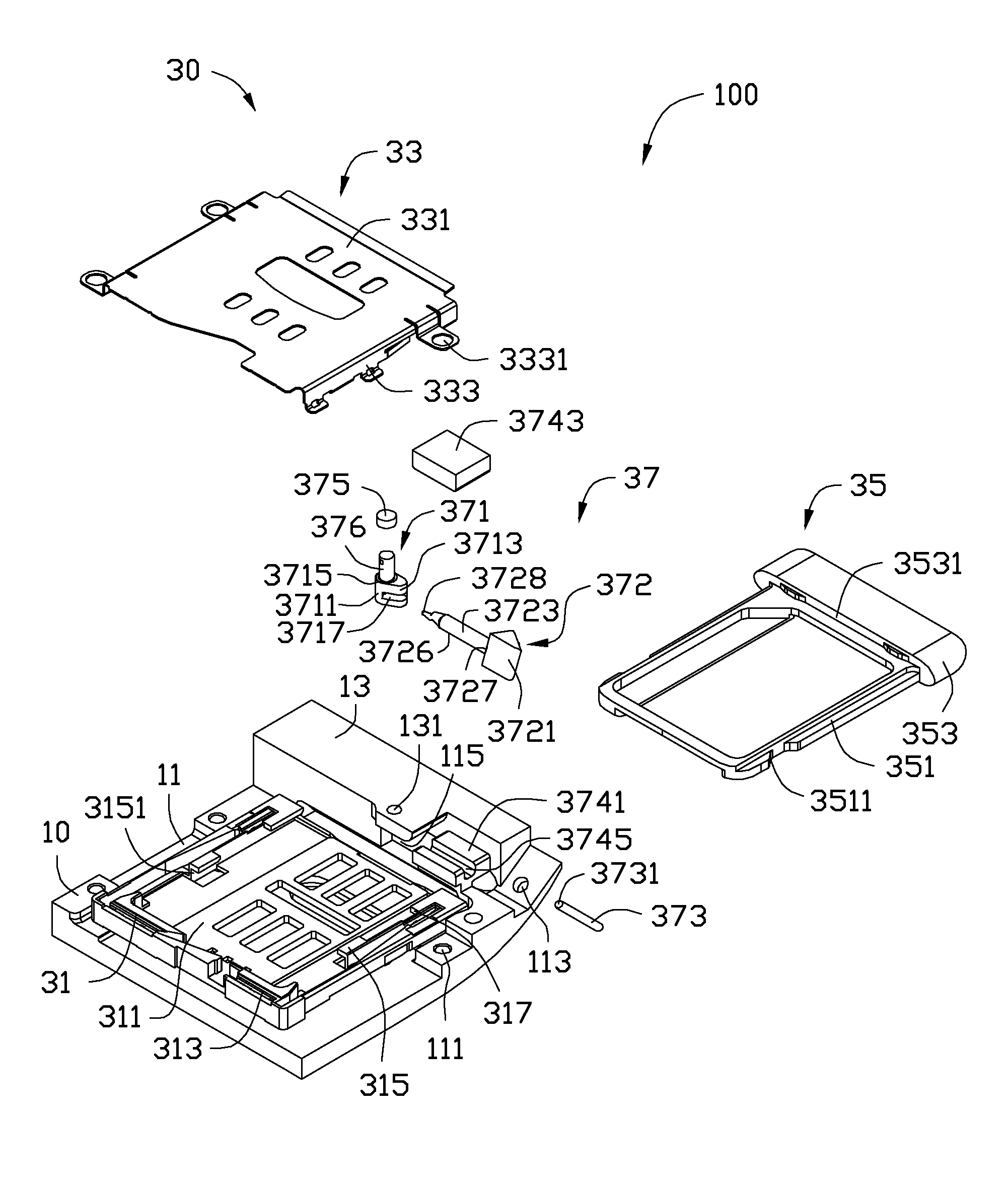
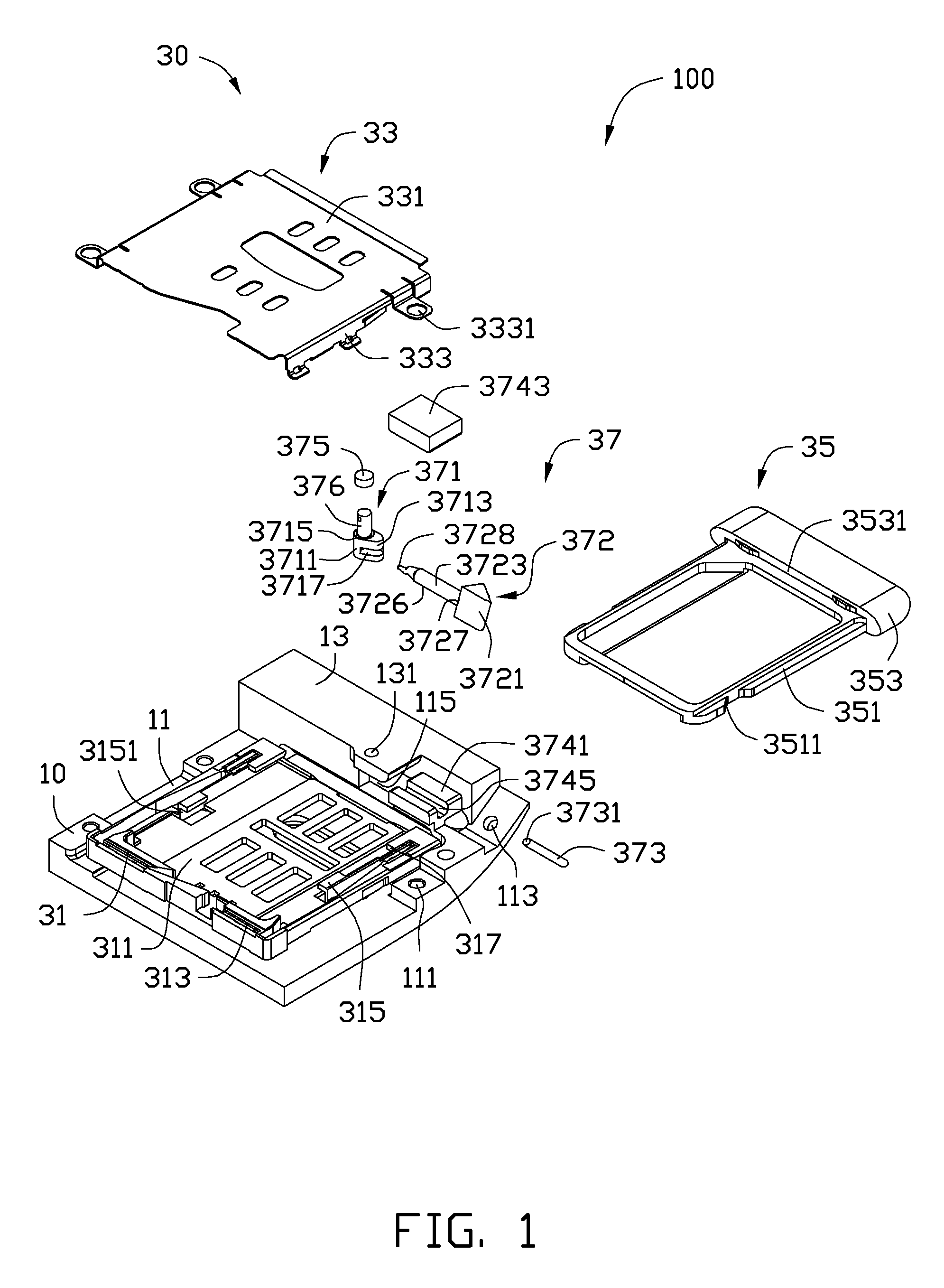
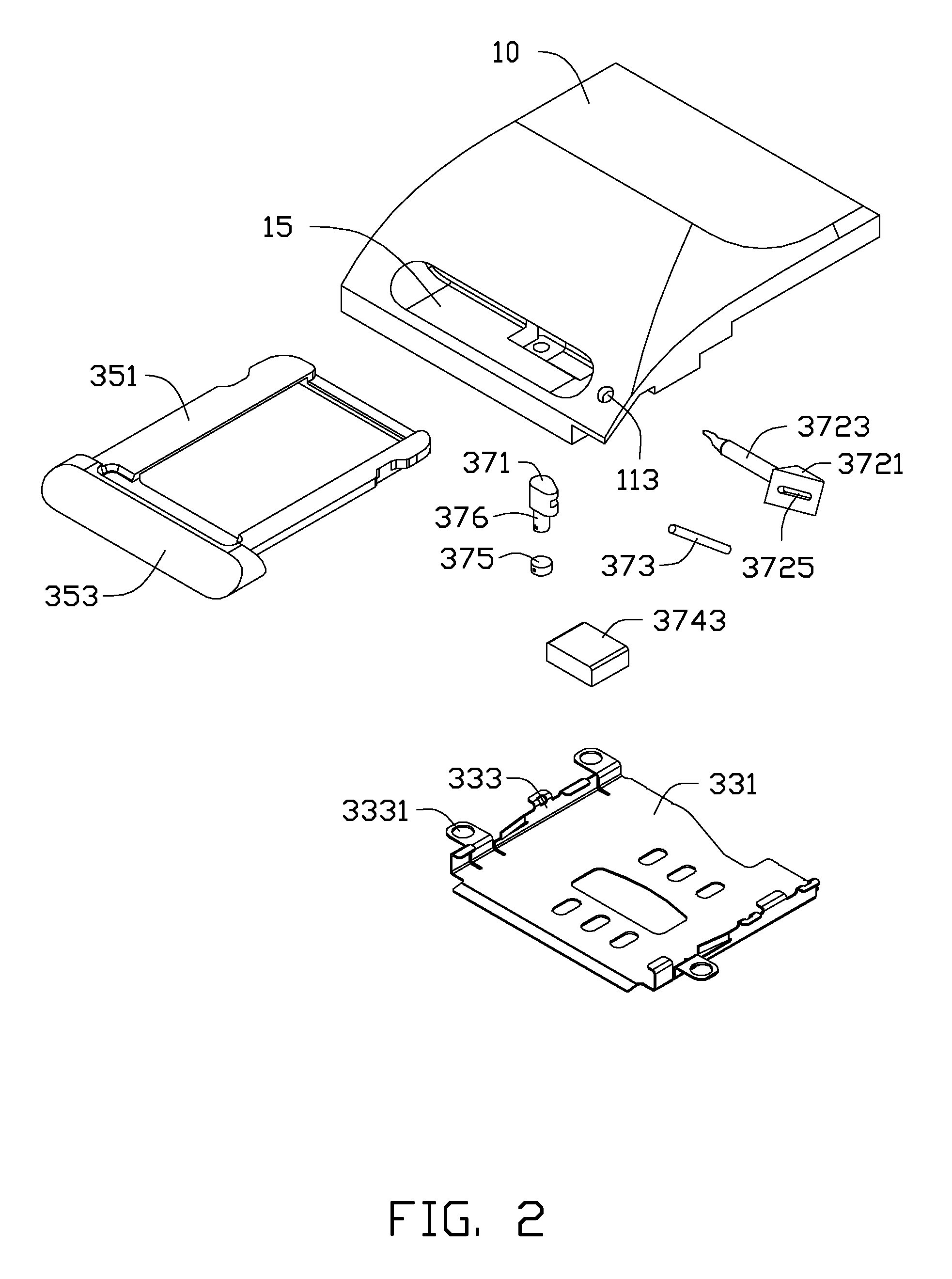
[0011]Referring to FIGS. 1 and 2, an embodiment of a portable electronic device 100 includes a housing 10 (partially shown in the FIGS. 1 and 2), and a chip card holding mechanism 30 mounted on the housing 10 for holding a chip card (not shown). The portable electronic device 100 includes various modules for performing specific functions. However, for simplicity, only the modules related to the chip card holding mechanism 30 are described. The portable electronic device 100 may be a mobile phone, a tablet computer, or other electronic device. The chip card may be one of various types of cards such as an SD Card, a multimedia card (MMC Card), or a SIM Card. In the illustrated embodiment, the electronic device 100 is a tablet computer, and the chip card is a SIM card.

[0012]The housing 10 includes a support portion 11 and a fixing portion 13 formed on one end of the support portion 11. The support portion 11 and the fixing portion 13 cooperatively define a receiving space 115 for assem...


PUM


Abstract

A portable electronic device includes a housing and a chip card holding mechanism assembled within the housing. The housing defines a mounting slot and an unlocking hole adjacent to the mounting slot. The chip card holding mechanism includes a support base assembled adjacent to the mounting slot, a receiving tray and an unlocking assembly. The receiving tray is slidably mounted on the support base and includes a tray body and an operating portion formed at one end of the tray body. The operating portion has a resisting surface. The unlocking assembly includes a cam body rotatably assembled to the housing and a driving member. The cam body forms a cam resisting portion resisting against the resisting surface of the receiving tray. The driving portion is inserted into the unlocking hole for driving the cam body to rotate thereby ejecting the receiving tray.

Description

BACKGROUND[0001]1. Technical Field[0002]The present disclosure relates to holding mechanisms, particularly to a chip card holding mechanism for a portable electronic device.[0003]2. Description of Related Art[0004]Portable electronic devices such as mobile phones and tablet computers, typically employ at least one chip card (e.g., SIM card) to perform multiple functions including storing information, connecting to the internet, and dialing calls. It is necessary to provide a chip card holding mechanism for holding / securing the chip card within the portable electronic device. The chip card holding mechanism usually defines a receiving space, an elastic sheet fitted in the receiving space, and a holding portion rotatably assembled on the housing of the portable electronic device. The chip card can be received and held in the receiving space by the holding member, with the chip card resisting the elastic sheet. When detaching or replacing the chip card, the user must detach the outer c...

Claims


Application Information

Patent Timeline
Patent Type & Authority Patents(United States)
IPC IPC(8): H05K5/00
CPCG06K7/04H01R13/639H01R13/629H01R12/71G06K13/085
Inventor DUAN, JU-PINGLUO, MING-FUSHI, FA-GUANG
Owner FU TAI HUA IND SHENZHEN
Learn More