Brake wear control system

a technology of wear control and brakes, applied in the direction of braking components, aircraft stabilisation, navigation instruments, etc., can solve the problems of uneven wear of brakes, increased maintenance costs, and increased maintenance costs of brakes on the same landing gear, so as to achieve more frequent inspections and maintenance, and reduce the effect of loss of revenu

Active Publication Date: 2014-01-21
THE BF GOODRICH CO
View PDF26 Cites 12 Cited by
  • Summary
  • Abstract
  • Description
  • Claims
  • Application Information

AI Technical Summary

Benefits of technology

[0007]Aircraft brakes are not only used to stop the aircraft, but also to steer the aircraft during taxing. As a result, brake wear may be uneven between landing gear. Further, due to differences between brakes (e.g., tolerances, exposure to the elements, variations in the coefficient of friction, differences in wear characteristics, etc.), brakes on the same landing gear may experience different wear rates. This can be problematic, as the brakes require more frequent inspections and maintenance than if they wore evenly. The increased number of inspections not only adds cost associated with maintenance personnel, but the inspections also can prevent use of the aircraft, resulting in lost revenue.
[0015]Additionally, the method can include predicting when the friction material for each brake will require replacement or maintenance, as well as managing wear by instructing movement of at least one brake from one landing gear to another landing gear to allow for a consistent level of wear.

Problems solved by technology

As a result, brake wear may be uneven between landing gear.
Further, due to differences between brakes (e.g., tolerances, exposure to the elements, variations in the coefficient of friction, differences in wear characteristics, etc.), brakes on the same landing gear may experience different wear rates.
This can be problematic, as the brakes require more frequent inspections and maintenance than if they wore evenly.
The increased number of inspections not only adds cost associated with maintenance personnel, but the inspections also can prevent use of the aircraft, resulting in lost revenue.

Method used


Image

  • Brake wear control system
  • Brake wear control system
  • Brake wear control system

Examples


Embodiment Construction

[0024]The principles of the invention will now be described with reference to the drawings. Because the invention was conceived and developed for use in an aircraft braking system, it will be herein described chiefly in this context. However, the principles of the invention in their broader aspects can be adapted to other types of braking systems, such as automobile brakes, truck brakes, etc where wear is managed on the front and back of brakes.

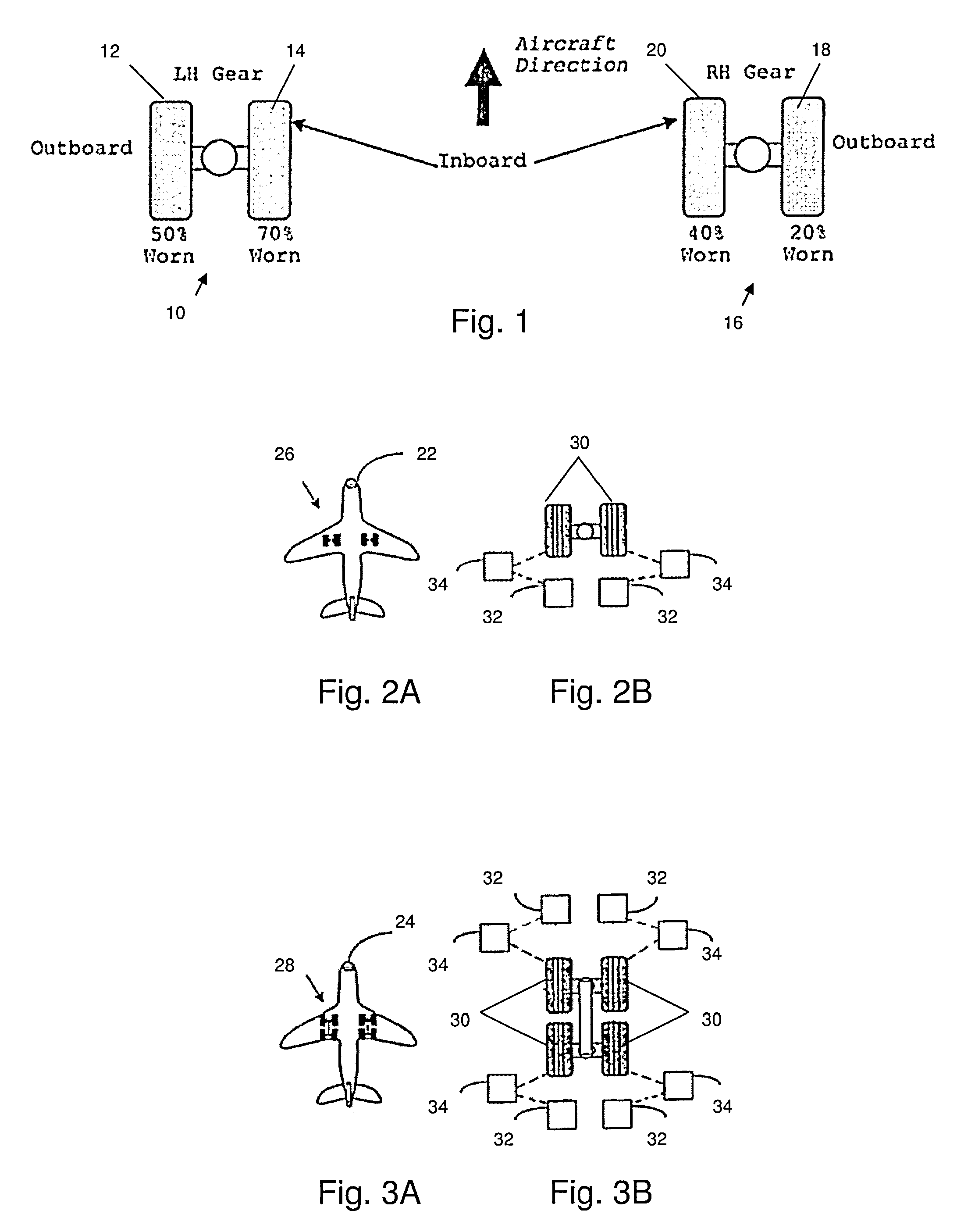
[0025]As noted above, a problem with conventional brake systems, such as aircraft brake systems, is that the friction material for one or more brakes may wear at a different rate than that of other brakes. As used herein, friction material refers to the consumable portion of the brake that is used to convert kinetic energy into heat energy and may include a carbon material, steel, ceramic, etc.

[0026]With reference to FIG. 1, there is shown two exemplary twin landing gears 10 and 16 having different amounts of available friction material for e...


PUM


Abstract

A system, apparatus and method provide a means for managing wear of brake friction material such that even friction material wear is experienced between brakes. The available friction material of each brake is monitored to determine an amount of wear. Based on the amount of wear, a braking force applied by each brake may be varied to ensure even wear between brakes.

Description

FIELD OF THE INVENTION[0001]The present invention relates generally to brake systems, and more particularly to a brake system for managing brake wear.BACKGROUND[0002]Known in the prior art are aircraft wheel and brake assemblies including a non-rotatable wheel support, a wheel mounted to the wheel support for rotation, and a brake disk stack having front and rear axial ends and alternating rotor and stator disks mounted with respect to the wheel support and wheel for relative axial movement. Each rotor disk is coupled to the wheel for rotation therewith and each stator disk is coupled to the wheel support against rotation. A back plate is located at the rear end of the disk pack and a brake head is located at the front end. The brake head houses a plurality of actuators that extend to compress the brake disk stack against the back plate. Torque is taken out by the stator disks through a static torque tube or the like.[0003]Each stator disk includes a friction material that engages t...

Claims


Application Information

Patent Timeline
Patent Type & Authority Patents(United States)
IPC IPC(8): G06F19/00F16D55/36
CPCB60T8/00F16D2066/003B60T17/221B64C25/42F16D66/026B60T8/26F16D55/24F16D66/02
Inventor CAHILL, ERIC, D.
Owner THE BF GOODRICH CO
Why Eureka
Try Eureka