Method of manufacturing a high-pressure discharge lamp

a manufacturing method and high-pressure discharge technology, applied in the manufacture of electric discharge tubes/lamps, electrode assembly manufacture, electric discharge system manufacture, etc., can solve the problems of difficult pressure application, failure of tungsten electrodes themselves, and electrodes which oppose each other in the lamp, so as to improve the reliability of the resulting electric connection and the reliability of the lamp

Inactive Publication Date: 2007-01-30
USHIO DENKI KK
View PDF7 Cites 2 Cited by
  • Summary
  • Abstract
  • Description
  • Claims
  • Application Information

AI Technical Summary

Benefits of technology

[0011]It is an object of the present invention to provide a method of manufacturing a high-pressure discharge lamp (ultra high-pressure mercury lamp) which is capable of eliminating the disadvantages found in the resistance welding of a tungsten electrode to a molybdenum foil as described above, facilitating the welding of both, and improving the reliability of the resulting electric connection and the reliability of the lamp itself.
[0018]The foregoing welding method can bond the tungsten electrode to the molybdenum foil with a smaller bonding area, unlike the conventional technique which involves sandwiching a tungsten electrode and a molybdenum foil in layers between welding electrodes of a resistance welding machine, thereby making it possible to reduce cracks which can occur in a portion of the glass sealed with the molybdenum foil.
[0019]In conventional resistance welding, electrode shafts can be bent or broken due to pressure applied thereto during welding when using tungsten electrodes that have shafts which are reduced in diameter. The present invention can eliminate such problems, and therefore avoid eccentricity between the electrodes of the lamp (see FIG. 1) due to bent electrode shafts.
[0020]In conventional resistance welding, the melted tungsten electrode and molybdenum foil stick to the welding rods of the resistance welding machine, and the welding rods significantly wear out, so that frequent maintenance is required for the welding machine, thus making the welding process unsuitable for automatization. The present invention, therefore, facilitates transition to automation.
[0021]When a laser is used, as in the present invention, both materials can be melted into a mixture, thus improving the reliability of the electrical connection and increasing the bonding strength.
[0022]Further, the present invention improves control of laser power and laser irradiated points, and can therefore reduce variations in welding strength.

Problems solved by technology

However, in the method of welding a tungsten electrode shaft to a molybdenum foil using a resistance welding machine, the tungsten electrode shaft can be bent, broken, or collapsed at a point applied with pressure, resulting in failure of the tungsten electrode itself, and eccentricity (see FIG. 1) of the electrodes which oppose each other within the lamp.
In addition, even the application of pressure can be difficult for a tungsten electrode shaft having a small diameter.
Also, the melted tungsten electrode and molybdenum foil can stick to the welding rods (welding electrodes) of the resistance welding machine, and the welding rods can significantly wear out, so that frequent maintenance is required for the welding machine, making the welding process unsuitable for automatization.
Further, since the resistance welding encounters difficulties in the application of pressure to a small point, the molybdenum foil must be welded to the tungsten electrode over a wide area.
Thus, when the molybdenum foil with the tungsten electrode welded thereto is sealed with glass, a large crack occurs in a portion of the glass sealed with the molybdenum foil, possibly resulting in defective air-tight sealing of the lamp due to the growth of the crack, and a bursting of the lamp when it is turned on.
Notably, the method of indirectly welding a tungsten electrode and a molybdenum foil with platinum or the like interposed therebetween, as described in the aforementioned JP-6-223783-A and JP-10-334789-A, entails an increased number of manufacturing steps and a higher cost.

Method used


Image

  • Method of manufacturing a high-pressure discharge lamp
  • Method of manufacturing a high-pressure discharge lamp
  • Method of manufacturing a high-pressure discharge lamp

Examples


Embodiment Construction

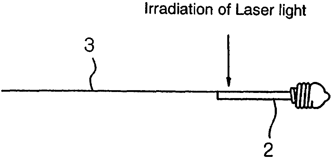
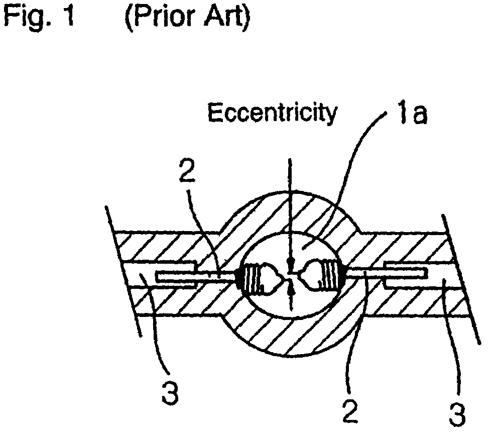
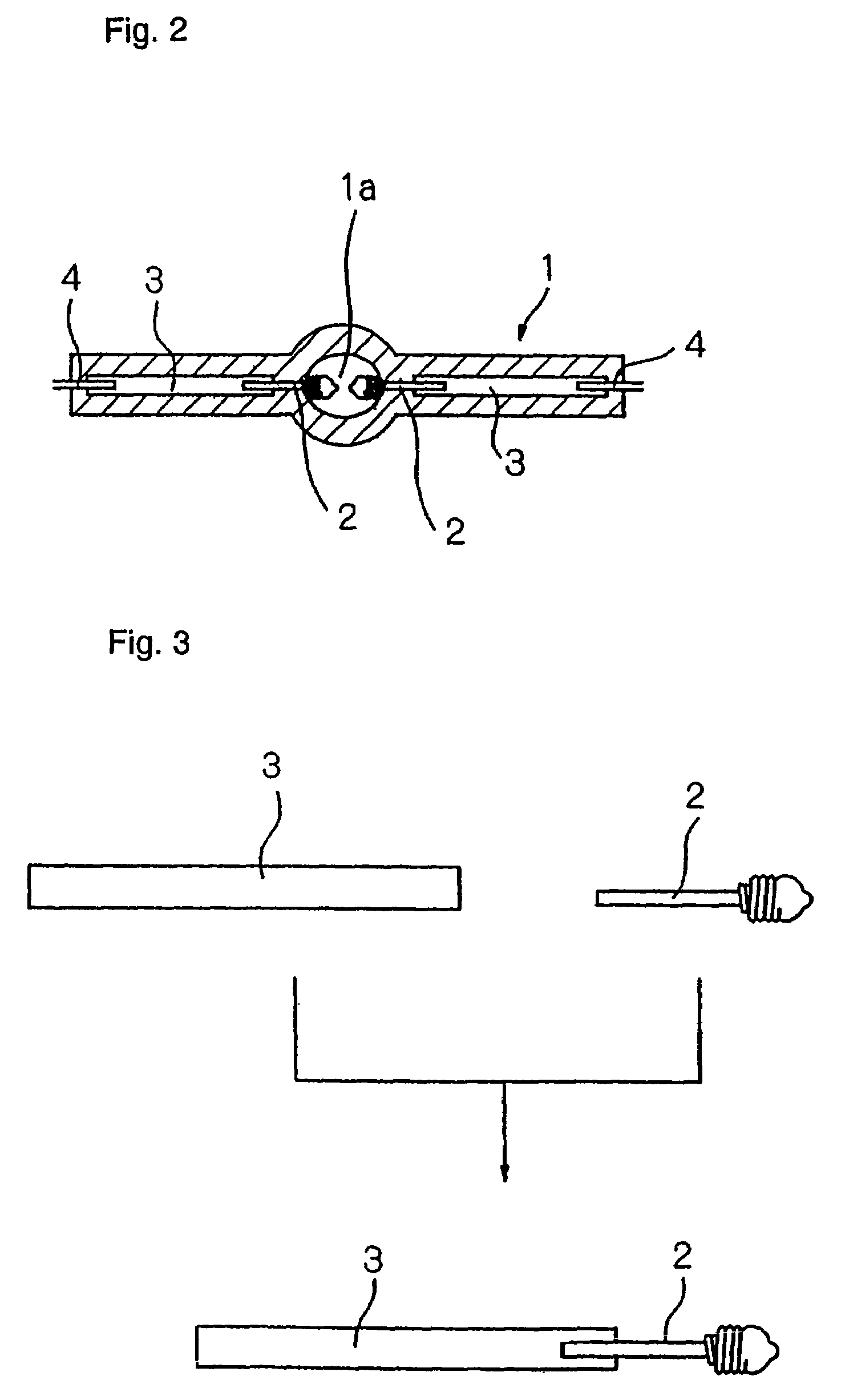
[0033]Referring first to FIG. 2, an ultra high-pressure mercury lamp, in one embodiment of the present invention, comprises lamp tube 1 made of quartz glass and having a central section formed in a spherical shape, and a pair of tungsten electrodes 2 arranged opposite to each other in central spherical space (discharge chamber) 1a of lamp tube 1. Each of tungsten electrodes 2 is connected to external lead wire 4 of a molybdenum rod through molybdenum foil (Mo foil) 3. Such an electrode assembly has part of tungsten electrode 1, molybdenum foil (Mo foil) 3, and part of external lead wire 4 sealed with quartz glass at one end of lamp tube 1. In this way, spherical space 1a of lamp tube 1 is hermetically sealed. While the illustrated lamp is intended for AC lighting, it can be used for DC lighting when an electrode functioning as an anode is made larger than an electrode functioning as a cathode.

[0034]Mercury, and an inert gas containing a halogen gas component are enclosed in spherica...


PUM

PropertyMeasurementUnit
angleaaaaaaaaaa
pressureaaaaaaaaaa
angleaaaaaaaaaa

Abstract

For manufacturing a high-pressure discharge lamp, a tungsten electrode is welded to a molybdenum foil by bringing a shaft of tungsten electrode into close contact with the molybdenum foil, and by irradiating a laser light, having a metal melting wavelength, to a junction of the molybdenum foil with the tungsten electrode from a location closer to the molybdenum foil to melt both the molybdenum foil and the shaft of the tungsten electrode for bonding.

Description

BACKGROUND OF THE INVENTION[0001]1. Field of the Invention[0002]The present invention relates to a method for manufacturing a high-pressure discharge lamp.[0003]2. Description of the Related Art[0004]General high-pressure discharge lamps such as an ultra high-pressure mercury lamp comprise an elongated cylindrical quartz glass tube which is comprised of a hollow spherical section, straight tube sections formed at both ends of the hollow spherical section, and electrode assemblies, each of which has an electrode that is partly embedded in an associated straight tube section and is opposite the electrode of the other electrode assembly in the spherical section. Each of the electrode assemblies has a molybdenum foil, a tungsten electrode shaft welded at one end of the molybdenum foil, and an external lead wire welded at the other end of the molybdenum foil. Then, the molybdenum foil, as well as part of the tungsten electrode and part of the external lead wire, welded at both ends of th...

Claims


Application Information

Patent Timeline
Patent Type & Authority Patents(United States)
IPC IPC(8): H01J9/00H01J9/14H01J9/28H01J9/18H01J9/20H01J9/36H01J61/073H01J61/36
CPCH01J9/36
Inventor MIZOBE, NORIMASA
Owner USHIO DENKI KK
Why Eureka
Try Eureka