
Image recording apparatus and method of adjusting recording head in image recording apparatus

a recording apparatus and recording head technology, applied in the direction of inking apparatus, power drive mechanism, printing, etc., can solve the problems of no standard head to apply, similar displacement of replacement heads, etc., and achieve the effect of adjusting the fluctuation of each head modul

Inactive Publication Date: 2014-01-28
FUJIFILM CORP
View PDF16 Cites 3 Cited by
  • Summary
  • Abstract
  • Description
  • Claims
  • Application Information

AI Technical Summary

Benefits of technology

The present invention relates to a device that evaluates the displacement between a recording head and a reference line on a conveyance device. This is done by using a sensor to read the output image and the reference line. This allows for highly accurate adjustment of the recording head based on the reference, without any operation errors. Additionally, the invention corrects the timing for each head module to ensure consistent performance. This ensures that any fluctuations in the performance of each head module can be corrected based on the accurate reference.

Problems solved by technology

However, it is disadvantageous in that if the standard head has been displaced, the replaced heads are similarly displaced since the amount of displacement is calculated with respect to the standard head.
An additional problem is that, when replacing all of the recording heads, there is no standard head to apply.

Method used


Image

  • Image recording apparatus and method of adjusting recording head in image recording apparatus
  • Image recording apparatus and method of adjusting recording head in image recording apparatus
  • Image recording apparatus and method of adjusting recording head in image recording apparatus

Examples


first embodiment

[0121]Timing adjustments for the respective modules of the inkjet heads and positional adjustments of the inkjet heads according to a first embodiment of the present invention are described below.

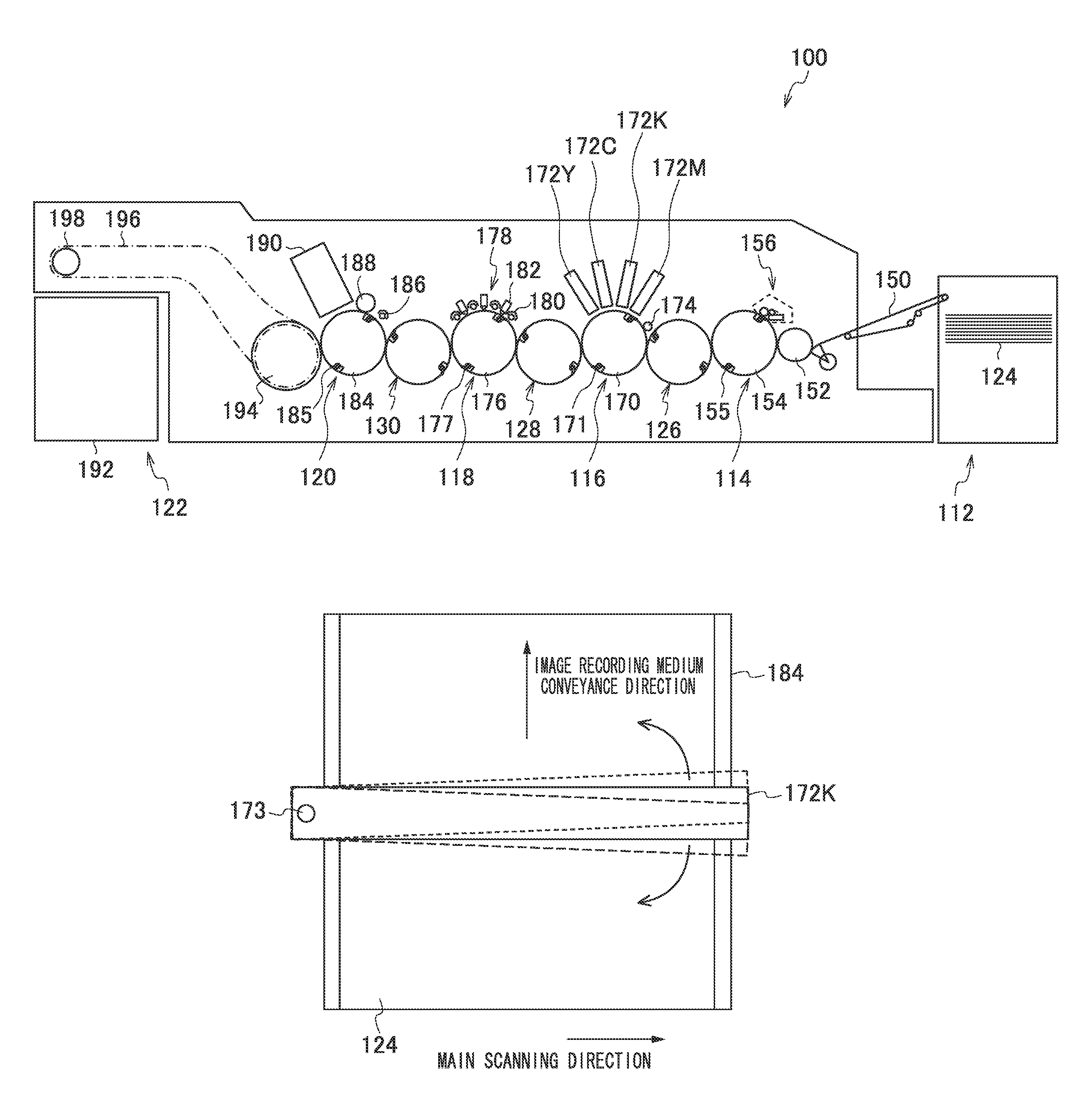
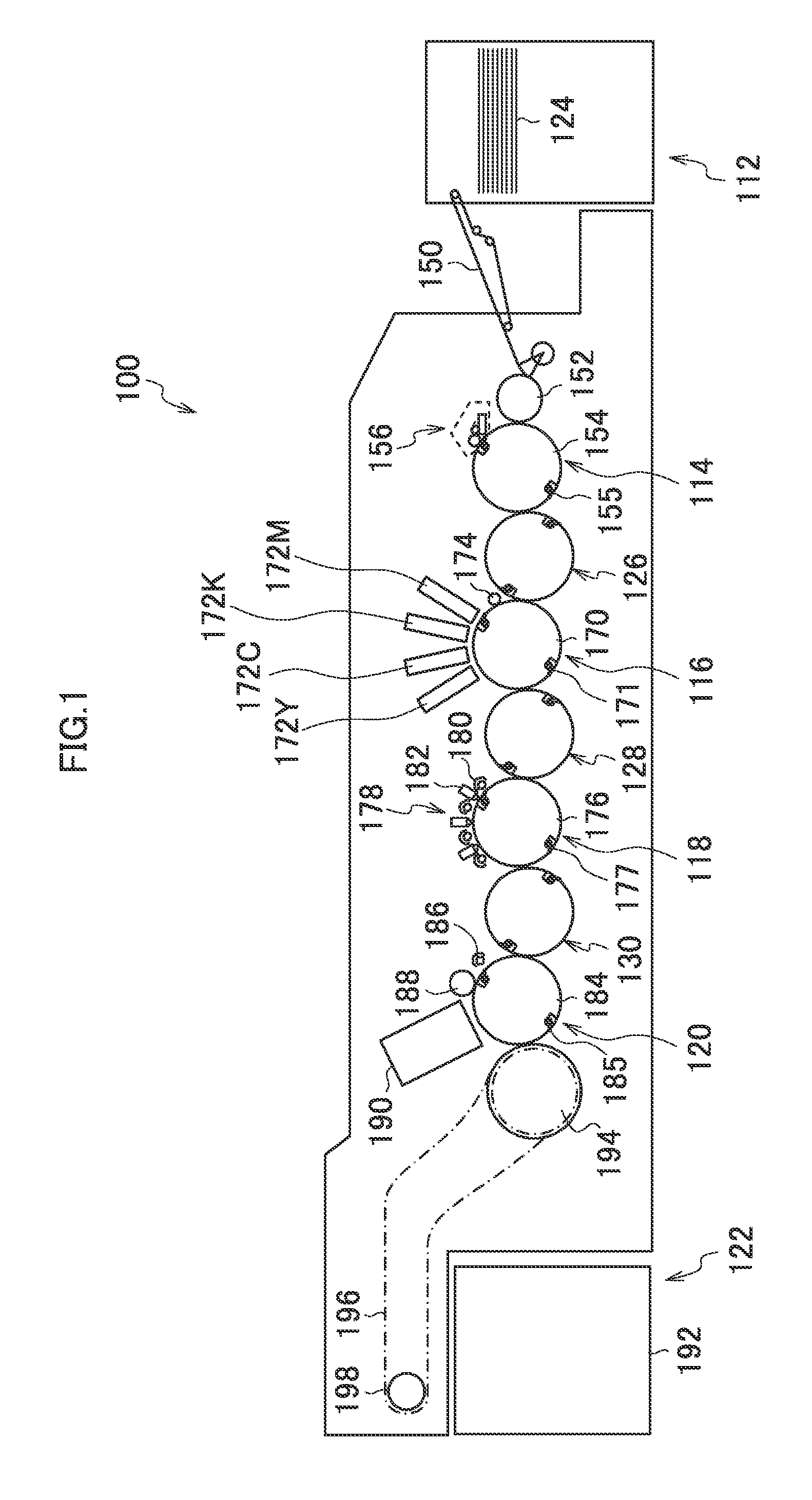
[0122]As illustrated in FIG. 7, the surface of the fixing drum 184 is covered with the ceramics jacket 400 in which a ceramics layer is formed on a stainless-steel substrate (e.g., SUS304). A surface of the ceramics jacket 400 has marked lines 410, which form a grid pattern of a plurality of vertical lines and horizontal lines intersecting vertically with one another. The ceramics jacket 400 is attached to the fixing drum 184 such that the vertical and horizontal lines of the grid pattern become line segments that are perpendicular or parallel to the rotary shaft of the fixing drum 184. In other words, of the marked lines 410, the line segments that are parallel to the rotary shaft of the fixing drum 184 are perpendicular to the paper conveyance direction.

[0123]The marked lines 410 are not ...

second embodiment

[0145]In the first embodiment, it has been described to replace the K inkjet head 172K only. However, adjustments can be performed by the same procedures even when attaching all of the inkjet heads 172 at the time of manufacturing or replacing two or more of the inkjet heads 172 after shipment.

[0146]FIG. 12 is a flowchart illustrating a method of adjusting the inkjet heads according to a second embodiment.

[0147]As with the first embodiment, first, the conveyance speed is set lower than the normal speed (step S201), and the marked lines 410 that are arranged on the ceramics jacket 400 wrapped around the fixing drum 184 are read by the in-line sensor 190 (step S202). The position reference data are generated from the read data on the marked lines 410.

[0148]Next, all of the inkjet heads 172 to be adjusted are driven to eject the inks to draw straight lines along the main scanning direction on an output sheet (step S203), and these straight lines are then read by the in-line sensor 190 ...


PUM


Abstract

The image recording apparatus includes: a recording head in which a plurality of recording elements are arranged over a length corresponding to a recordable width of a recording medium; a conveyance device which performs conveyance to cause the recording head and the recording medium to move relatively to each other one time only in a conveyance direction, a reference line being arranged on the conveyance device; an image output device which records a prescribed image on the recording medium through the recording head; a sensor which reads the reference line on the conveyance device, and reads the prescribed image on the recording medium recorded by the image output device; and a displacement evaluation device which evaluates a displacement between the reference line and the recording head in accordance with a result of reading the reference line by the sensor and a result of reading the prescribed image by the sensor.

Description

BACKGROUND OF THE INVENTION[0001]1. Field of the Invention[0002]The present invention relates to an image recording apparatus and a method of adjusting a recording head in an image recording apparatus, more particularly to technology for adjusting a recording timing of a recording head and a position to attach the recording head.[0003]2. Description of the Related Art[0004]For an image recording apparatus with a recording head in which a plurality of nozzles for ejecting ink are arranged, there have been proposed many technologies for correcting an attachment position to attach the recording head, in order to prevent uneven printing that is caused by the displacement of the attachment position of the recording head when the image recording apparatus is vibrated upon transportation thereof or when the recording head is replaced.[0005]Japanese Patent Application Publication No. 07-323582, for example, discloses an image forming apparatus based on an inkjet recording system that forms ...

Claims


Application Information

Patent Timeline
Patent Type & Authority Patents(United States)
IPC IPC(8): B41J29/38
CPCB41J2/2146B41J2202/21B41J2/2139B41J2025/008
Inventor SAITA, HIROFUMI
Owner FUJIFILM CORP
Learn More