AI technical title is built by Patsnap AI team. It summarizes the technical point description of the patent document.
a laser tracker and laser scanner technology, applied in the direction of distance measurement, instruments, using reradiation, etc., can solve the problem of distance information being los
Active Publication Date: 2014-01-28
FARO TECH INC
View PDF476 Cites 18 Cited by
Summary
Abstract
Description
Claims
Application Information
AI Technical Summary
This helps you quickly interpret patents by identifying the three key elements:
Problems solved by technology
Method used
Benefits of technology
Benefits of technology
The present invention is a laser scanner or tracker that includes a light source and a data capture component for capturing light reflected from the environment. It also includes a projector integrated within the laser scanner or tracker, which can project visible information onto objects in the environment. This information can include design intent, data captured by the laser scanner or tracker, or guidance for an operator. The technical effect of this invention is to enable improved visual acuity and efficiency in identifying and measuring objects in a laser-based system.
Problems solved by technology
If the beam is broken during the measurement, the number of counts cannot be accurately known, causing the distance information to be lost.
Method used
Image
Click on the blue label to locate the original text in one second.
Reading with bidirectional positioning of images and text.
Examples
Embodiment Construction
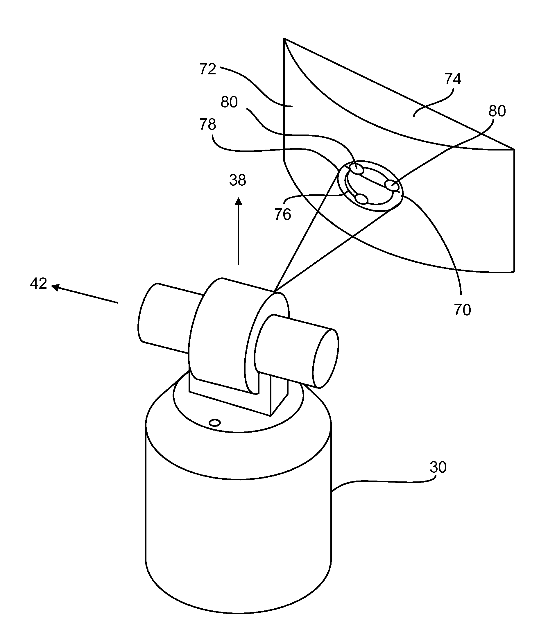
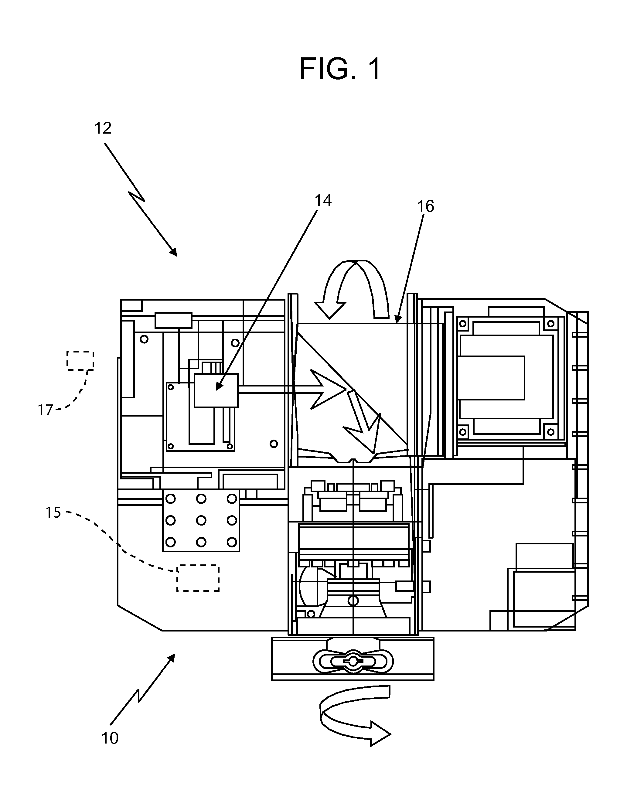
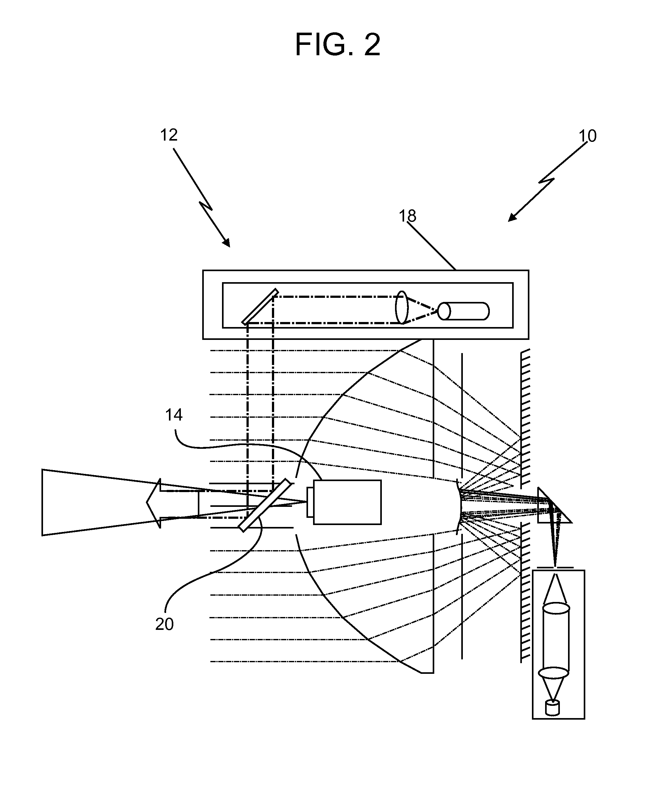
[0028]Referring to FIG. 1, in accordance with embodiments of the present invention, there illustrated is a rotating scanning head portion 10 of a laser scanner 12 having a commercially available, relatively small or “miniature,”“ultraminiature,” or “pico” projector 14 integrated directly within the optical components (“optics”) located within the scanner head 10. The projector 14 may contain some amount of processing capability, as is known. The projector 14 may be connected with, or in communication with, a first computer or processor 15 of the laser scanner 12, where the computer or processor may be integral with the scanner 12 (e.g., located within the scanner head 10) or may be a second separate computer or processor 17 therefrom (e.g., a laptop computer). The scanner head 10 is typically mounted to a supporting tripod (not shown), which sits on the ground or other surface during laser scanner use. As described in more detail with respect to FIG. 2, the projector 14 sends variou...
PUM
Abstract
A laserscanner or a laser tracker includes a light source that emits a light beam within an environment, and a data capture component that captures the light beam reflected back to the laserscanner or tracker from the environment. The laser scanner or tracker also includes a projector integrated within a body of the laser scanner or tracker or mounted to the body of the laser scanner or tracker at a predetermined location, the projector being operable to project visible information onto an object located within the environment, the projected visible information being indicative of images, data or information, the projected visible information being at least one of design intent information, information acquired by the laser scanner or tracker, or guidance to an operator.
Description
CROSS-REFERENCE TO RELATED APPLICATIONS[0001]This application claims priority to U.S. Provisional Application No. 61 / 380,869, filed on Sep. 8, 2010; and to U.S. Non-Provisional application Ser. No. 13 / 006,507, filed on Jan. 14, 2011; which claims the benefit of priority to U.S. Provisional Application No. 61 / 296,555 filed on Jan. 20, 2010, to U.S. Provisional Application No. 61 / 351,347 filed on Jun. 4, 2010 and to U.S. Provisional Application No. 61 / 355,279 filed on Jun. 16, 2010. The present application also claims priority to U.S. Non-Provisional application Ser. No. 13 / 006,468, filed on Jan. 14, 2011; which claims the benefit of priority to U.S. Provisional Application No. 61 / 296,555 filed on Jan. 20, 2010, to U.S. Provisional Application No. 61 / 351,347 filed on Jun. 4, 2010 and to U.S. Provisional Application No. 61 / 355,279 filed on Jun. 16, 2010. The present application also claims priority to U.S. Non-Provisional application Ser. No. 13 / 006,524, filed on Jan. 14, 2011; which c...
Claims
Application Information
Patent Timeline
Application Date:The date an application was filed.
Publication Date:The date a patent or application was officially published.
First Publication Date:The earliest publication date of a patent with the same application number.
Issue Date:Publication date of the patent grant document.
PCT Entry Date:The Entry date of PCT National Phase.
Estimated Expiry Date:The statutory expiry date of a patent right according to the Patent Law, and it is the longest term of protection that the patent right can achieve without the termination of the patent right due to other reasons(Term extension factor has been taken into account ).
Invalid Date:Actual expiry date is based on effective date or publication date of legal transaction data of invalid patent.

